
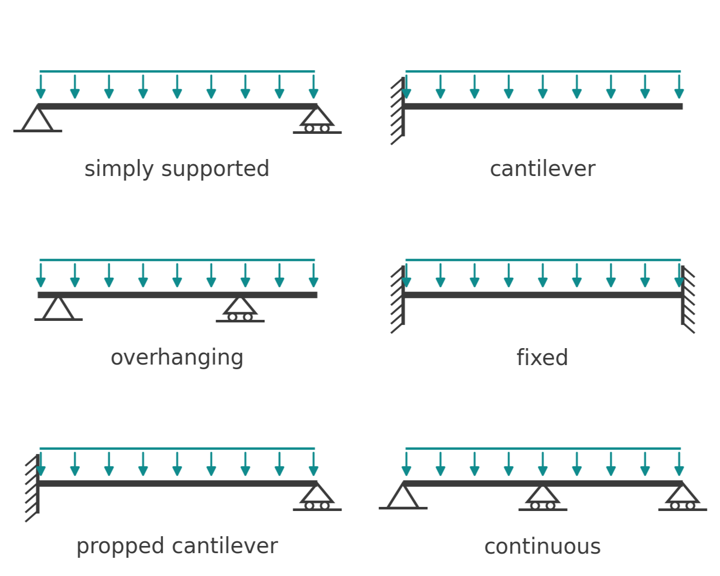
The main types of beams by support condition, how each one carries load, when it is statically determinate, and a worked comparison of moment and deflection.
Types of beams are usually sorted by how they are supported, because the supports decide how a beam behaves: where the bending moment peaks, whether it hogs or sags, how far it deflects, and whether you can analyse it with equilibrium alone. This guide covers the three support types, the seven common support arrangements built from them, how to tell a determinate beam from an indeterminate one, and a worked comparison that shows why a fixed-ended beam deflects one fifth as much as a simply supported beam of the same span.
What a beam is
A beam is a member that carries loads applied across its axis and delivers them to its supports by bending and shear. That distinguishes it from a column, which carries load along its axis, and from a truss, whose members carry axial force only. Floor joists, lintels, girders, purlins and bridge decks are all beams.
Under load a beam develops a shear force and a bending moment at every section. Their distribution along the span is what a shear force and bending moment diagram shows, and the support arrangement sets the shape of those diagrams.
Support types
Every beam type is a combination of three idealised supports:
- Pin: prevents vertical and horizontal movement, allows rotation. Two reactions.
- Roller: prevents vertical movement only. One reaction. A roller lets the beam expand and shorten freely.
- Fixed: prevents movement and rotation. Three reactions: vertical, horizontal and a moment.

Real connections sit somewhere between these. A bolted steel cleat behaves close to a pin; a beam cast monolithically into a concrete wall behaves close to fixed. Choosing the idealisation that matches the detail is part of the design.
Determinate or indeterminate
A plane beam has three equilibrium equations: vertical forces, horizontal forces and moments. If the supports provide exactly three unknown reactions, the beam is statically determinate and the reactions, shears and moments follow from equilibrium alone. More reactions than that make it statically indeterminate, and the extra unknowns need compatibility conditions: the slopes and deflections at the supports must match what the supports allow.
The degree of indeterminacy is the number of reactions minus three, minus one for each internal hinge. A simply supported beam has \( 3 - 3 = 0 \). A propped cantilever has \( 4 - 3 = 1 \). A fixed-ended beam has \( 6 - 3 = 3 \), or two if you ignore the axial restraint, which carries nothing under transverse load. A two-span continuous beam has \( 4 - 3 = 1 \).
Indeterminate beams are solved by moment distribution, the three-moment equation, the stiffness method or software, or more usually by looking up the standard result. The trade-off is worth it: indeterminate beams are stiffer and have lower peak moments, but they are sensitive to support settlement and temperature, and a fixed support only counts if the detail really does prevent rotation.
Types of beams by support condition
Simply supported beam
A pin at one end and a roller at the other. The end moments are zero, so the whole span sags and the peak moment sits where the shear crosses zero. Under a UDL \( w \) the midspan moment is \( wL^2/8 \) and the midspan deflection is \( 5wL^4/384EI \). It is the most common beam type and the baseline the others get compared with; the full set of load cases is on the simply supported beam formulas page.
Cantilever beam
Fixed at one end and free at the other. The free end carries no shear or moment and the whole beam hogs, with the peak moment \( wL^2/2 \) and the peak shear \( wL \) at the root. The tip deflection under a UDL is \( wL^4/8EI \). Balconies, canopies, sign posts and retaining wall stems are cantilevers. See the cantilever beam formulas for point loads and partial loads.
Overhanging beam
A simply supported span that continues past one or both supports. The overhang acts as a cantilever and produces a hogging moment over the support, which reduces the sagging moment in the main span. With one pin and one roller it is still determinate. Balconies carried on back-spanned joists are the usual example.
Fixed beam
Both ends fixed against rotation. Under a UDL the ends hog with \( wL^2/12 \) and the midspan sags with \( wL^2/24 \), so the largest moment is two thirds of the simply supported value, and the deflection \( wL^4/384EI \) is one fifth of it. This only holds if the supports are stiff enough to resist the end moments, which rules out most light steel connections.
Propped cantilever
Fixed at one end, roller or pin at the other, with one redundant. Under a UDL the fixed end hogs with \( wL^2/8 \) and the span sags with \( 9wL^2/128 \) at \( 3L/8 \) from the propped end. The maximum deflection is \( wL^4/185EI \). It is the model for a beam cast into a wall at one end and sitting on a steel beam at the other.
Continuous beam
One member over three or more supports. The interior supports attract hogging moments that relieve the spans. For two equal spans under a UDL the moment over the middle support is \( wL^2/8 \), the span moments are \( 9wL^2/128 \), and the reactions are \( 3wL/8 \) at the ends and \( 10wL/8 \) in the middle. Three, four and more spans follow the same pattern with coefficients that depend on the span ratios, which the continuous beam formulas page tabulates. Because the spans interact, pattern loading (live load on alternate spans) has to be checked.
Beams with internal hinges
A continuous beam fitted with hinges, sometimes called a Gerber beam, becomes determinate again: each hinge removes one unknown. The hinges are placed near the points of contraflexure so the moment diagram looks like the continuous one, while the structure stays insensitive to settlement. Bridge girders and precast systems use them.
Worked comparison: same span, different supports
The simply supported and cantilever rows below can be reproduced in the beam analysis pack using Macaulay's theorem, and the fixed-ended, propped and continuous rows in the continuous beam calculator, which takes pinned or fixed ends and any number of spans up to six.
Take a 5 m span carrying a UDL of 10 kN/m, with \( EI = 20\,000 \) kNm², which is a 200 GPa steel section with \( I = 100 \times 10^6 \) mm⁴. Working each case from the formulas above:
- Simply supported: \( M_{max} = 10 \times 5^2/8 = 31.25 \) kNm sagging; \( \delta = 5 \times 10 \times 5^4/(384 \times 20\,000) = 4.07 \) mm.
- Fixed both ends: \( M_{end} = 10 \times 5^2/12 = 20.83 \) kNm hogging, \( M_{mid} = 10.42 \) kNm sagging; \( \delta = 10 \times 5^4/(384 \times 20\,000) = 0.81 \) mm.
- Propped cantilever: \( M_{fixed} = 31.25 \) kNm hogging, \( M_{span} = 9 \times 10 \times 5^2/128 = 17.58 \) kNm; \( \delta = 10 \times 5^4/(185 \times 20\,000) = 1.69 \) mm.
- Cantilever: \( M_{root} = 10 \times 5^2/2 = 125 \) kNm hogging; \( \delta_{tip} = 10 \times 5^4/(8 \times 20\,000) = 39.06 \) mm.
- Two continuous 5 m spans: \( M_{support} = 31.25 \) kNm hogging, \( M_{span} = 17.58 \) kNm, the same as the propped cantilever by symmetry.

Fixing the ends cuts the peak moment by a third and the deflection by four fifths. Propping a cantilever changes it from the worst case to a modest one: the tip deflection drops from 39 mm to under 2 mm. The cantilever, with four times the moment and nearly ten times the deflection of the simply supported beam, is why cantilever spans are kept short.

Types of beams by section and material
The support condition sets the actions; the section and material set the capacity. The common families are:
- Steel I-sections (universal beams, IPE and HE sections) and hollow sections, designed to AS 4100 or EN 1993-1-1.
- Reinforced and prestressed concrete rectangular, T and L beams, designed to AS 3600 or EN 1992-1-1.
- Sawn, laminated veneer and glued laminated timber, designed to AS 1720.1 or EN 1995-1-1.
- Composite steel and concrete beams, where the slab acts as the compression flange.
Whatever the material, the stiffness in every formula above is \( EI \), so the second moment of area of the section matters as much as the support condition.
Serviceability
Deflection limits are set as a fraction of span and depend on what the beam supports. AS/NZS 1170.0 Appendix C gives suggested limits for the Australian and New Zealand context, and EN 1990 Annex A1.4 with the relevant National Annex does the same in Europe. Limits in the order of \( L/250 \) to \( L/360 \) are common for floors, with tighter values where brittle finishes sit on the beam. The deflection formulas above are what those limits get checked against.
Run it in CalcTree
The beam analysis pack using Macaulay's theorem and the continuous beam calculator between them run every case in the comparison live. Any of the cases above can be built as a live CalcTree page where the span, load and support type are inputs and the moments, shears and deflections are checkable outputs. The Beam Analysis Pack using Macaulay's Theorem covers the determinate cases, and the continuous beam analysis with OpenSees handles multi-span beams.





