
Simply supported beam moment and shear formulas for UDL, point loads, partial loads and end moments, with reactions, diagrams and two worked hand calculations.
Simply supported beam moment and shear formulas are the ones every structural engineer carries in their head: \(wL^2/8\), \(PL/4\) and the reactions that go with them. This page sets out the full set for the common load cases, with the reaction forces, the shear force at the supports, the bending moment at any point and where the maximum sits, then works through two hand calculations so you can see how they are used.
All formulas take sagging moment as positive and use \(x\) measured from the left support A. Shear is positive when the resultant of the forces to the left of the section acts upward.
What a simply supported beam is
A simply supported beam spans between two supports that resist vertical load but do not resist rotation. One support is a pin, which also holds the beam horizontally. The other is a roller, which lets the beam expand and contract along its length without building up axial force. The ends are free to rotate, so the bending moment at both supports is zero and the beam sags between them.
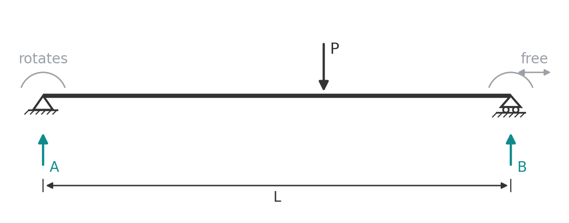
Three unknown reactions (vertical at A, vertical and horizontal at B) against three equations of equilibrium make the beam statically determinate. Reactions, shear and moment follow from statics alone, and the section size and material do not affect them. That is what makes these formulas universal: the same \(wL^2/8\) applies to a timber joist, a steel floor beam and a precast concrete plank.
In real buildings the simply supported model covers secondary floor beams on simple cleat or web-side-plate connections, purlins and rafters spanning between frames, precast planks on bearing, single-span bridge girders and most timber floor joists. Where a beam runs over several supports the behaviour changes: see continuous beam formulas. A beam fixed at one end only is covered by the cantilever beam formulas.
Uniformly distributed load
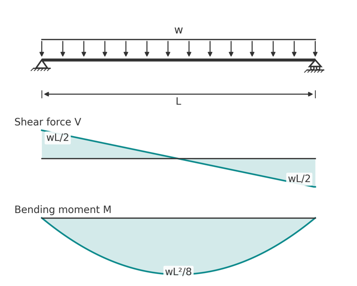
A UDL of \(w\) per unit length over the full span \(L\) is the self-weight case and the usual way floor and roof loads arrive at a beam.
$$ R_A = R_B = \frac{wL}{2} $$
$$ V(x) = w\left(\frac{L}{2} - x\right), \qquad V_{max} = \pm\frac{wL}{2} \text{ at the supports} $$
$$ M(x) = \frac{w x \left(L - x\right)}{2}, \qquad M_{max} = \frac{wL^2}{8} \text{ at midspan} $$
The shear diagram is a straight line from \(+wL/2\) to \(-wL/2\), crossing zero at midspan, and the moment diagram is a parabola with its peak where the shear is zero. That relationship, maximum moment where shear crosses zero, holds for every load case on this page.
Partial uniformly distributed load
Centred on midspan
For a UDL of \(w\) over a length \(a\) centred on midspan:
$$ R_A = R_B = \frac{wa}{2}, \qquad V_{max} = \frac{wa}{2}, \qquad M_{max} = \frac{wa\left(2L - a\right)}{8} \text{ at midspan} $$
Set \(a = L\) and this collapses to \(wL^2/8\).
Starting at one support
For a UDL of \(w\) over a length \(a\) starting at support A:
$$ R_A = \frac{wa\left(2L - a\right)}{2L}, \qquad R_B = \frac{wa^2}{2L} $$
$$ M_{max} = \frac{R_A^2}{2w} \quad \text{at } x = \frac{R_A}{w} $$
The maximum is inside the loaded length, where the shear reaches zero. Outside it the moment falls linearly to zero at B.
Point load at midspan
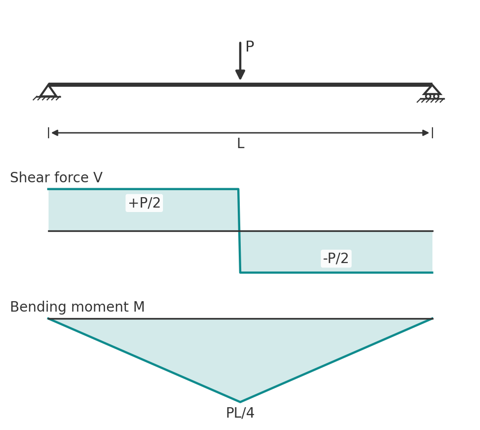
$$ R_A = R_B = \frac{P}{2}, \qquad V = +\frac{P}{2} \text{ left of the load}, \; -\frac{P}{2} \text{ right of it} $$
$$ M(x) = \frac{P x}{2} \text{ for } x \le \frac{L}{2}, \qquad M_{max} = \frac{PL}{4} \text{ at midspan} $$
The shear diagram is two rectangles and the moment diagram is a triangle. Compared with the same total load spread as a UDL (\(wL = P\)), the point load gives twice the moment, which is why concentrated loads from columns or secondary beams dominate a design.
Point load at any position
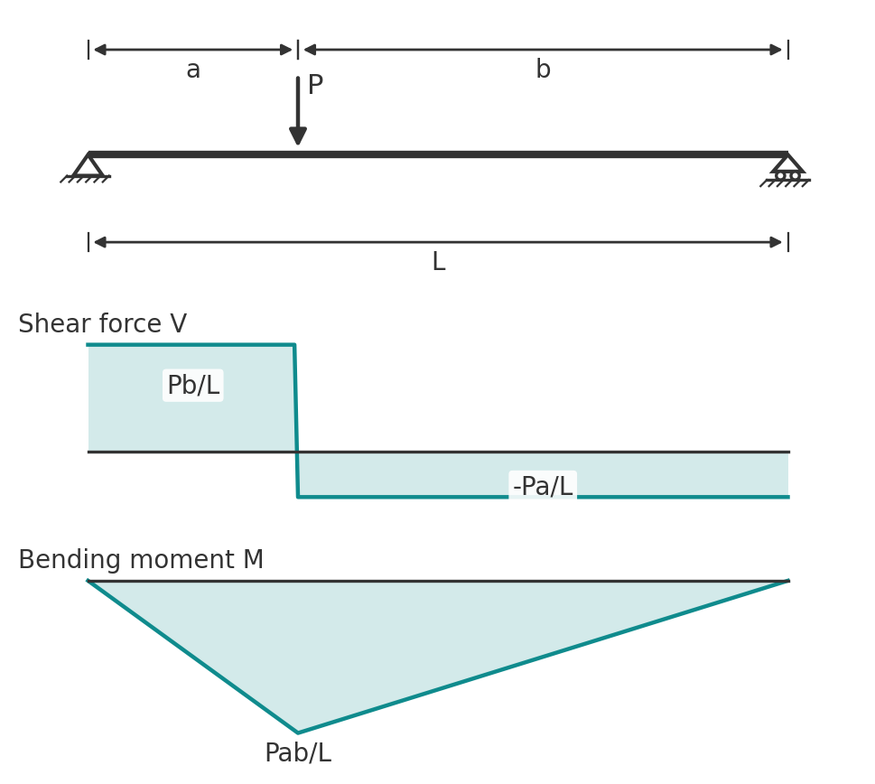
With the load at distance \(a\) from A and \(b = L - a\) from B:
$$ R_A = \frac{Pb}{L}, \qquad R_B = \frac{Pa}{L} $$
$$ M(x) = \frac{Pbx}{L} \text{ for } x \le a, \qquad M_{max} = \frac{Pab}{L} \text{ under the load} $$
The reaction at each support is the load times the fraction of the span on the far side, so the nearer support takes more. The shear is \(+Pb/L\) to the left of the load and \(-Pa/L\) to the right. The moment peaks under the load and is largest when the load is at midspan.
Two equal point loads, symmetric
Two loads \(P\) each at distance \(a\) from their nearest support (the four-point bending arrangement):
$$ R_A = R_B = P, \qquad V = \pm P \text{ outside the loads}, \; 0 \text{ between them} $$
$$ M_{max} = Pa \quad \text{constant between the loads} $$
For loads at the third points, \(M_{max} = PL/3\). Between the loads the beam is in pure bending with no shear, which is why this arrangement is used for bending tests.
Three equal point loads at the quarter points
$$ R_A = R_B = \frac{3P}{2}, \qquad V = \frac{3P}{2}, \; \frac{P}{2}, \; -\frac{P}{2}, \; -\frac{3P}{2} \text{ in the four segments} $$
$$ M_{max} = \frac{PL}{2} \text{ at midspan}, \qquad M = \frac{3PL}{8} \text{ under the outer loads} $$
Two point loads, not symmetric
There is no single neat formula, but the general case is quick by superposition. Take the reactions by moments about one support, then draw the shear diagram as a series of steps: it starts at \(R_A\), drops by each load as you pass it, and ends at \(-R_B\). The moment at any point is the area under the shear diagram up to that point, and the maximum is where the shear changes sign. The worked example below does exactly this for a UDL and a point load together.
Triangular load
For a load that increases linearly from zero at A to \(w_0\) at B:
$$ R_A = \frac{w_0 L}{6}, \qquad R_B = \frac{w_0 L}{3} $$
$$ M_{max} = \frac{w_0 L^2}{9\sqrt{3}} \approx 0.064\, w_0 L^2 \quad \text{at } x = \frac{L}{\sqrt{3}} \approx 0.577L $$
This is the hydrostatic case, and the pattern of a lateral earth or water pressure resolved onto a vertical member spanning between supports.
Moment applied at one end
A moment \(M_0\) applied at support A (for example from a cantilever extension beyond the support, or a connection that transfers some moment):
$$ R_A = -\frac{M_0}{L}, \qquad R_B = +\frac{M_0}{L} $$
$$ M(x) = M_0\left(1 - \frac{x}{L}\right), \qquad V = \frac{M_0}{L} \text{ constant} $$
The reactions form a couple that balances the applied moment, and the moment diagram is a straight line from \(M_0\) at A to zero at B.
Where the formulas sit in design
The formulas give you the design actions. The codes supply the factored loads that go in and the capacities the results are checked against.
- Load combinations: AS/NZS 1170.0 Clause 4.2.2 gives \(1.2G + 1.5Q\) for the strength limit state; EN 1990 Clause 6.4.3.2, Equation 6.10, gives \(1.35G + 1.5Q\). Characteristic floor live loads come from AS/NZS 1170.1 Table 3.1 and EN 1991-1-1 Table 6.2. See structural load calculations for the full build-up.
- Steel capacity: AS 4100 Clause 5.1 requires \(M^* \le \phi M_s\) for bending and Clause 5.11 covers shear. EN 1993-1-1 Clause 6.2.5 (bending) and Clause 6.2.6 (shear) are the equivalents.
- Concrete and timber: AS 3600 Section 8 and EN 1992-1-1 Section 6 for reinforced concrete beams; AS 1720.1 and EN 1995-1-1 for timber.
Worked example 1: floor beam under a UDL
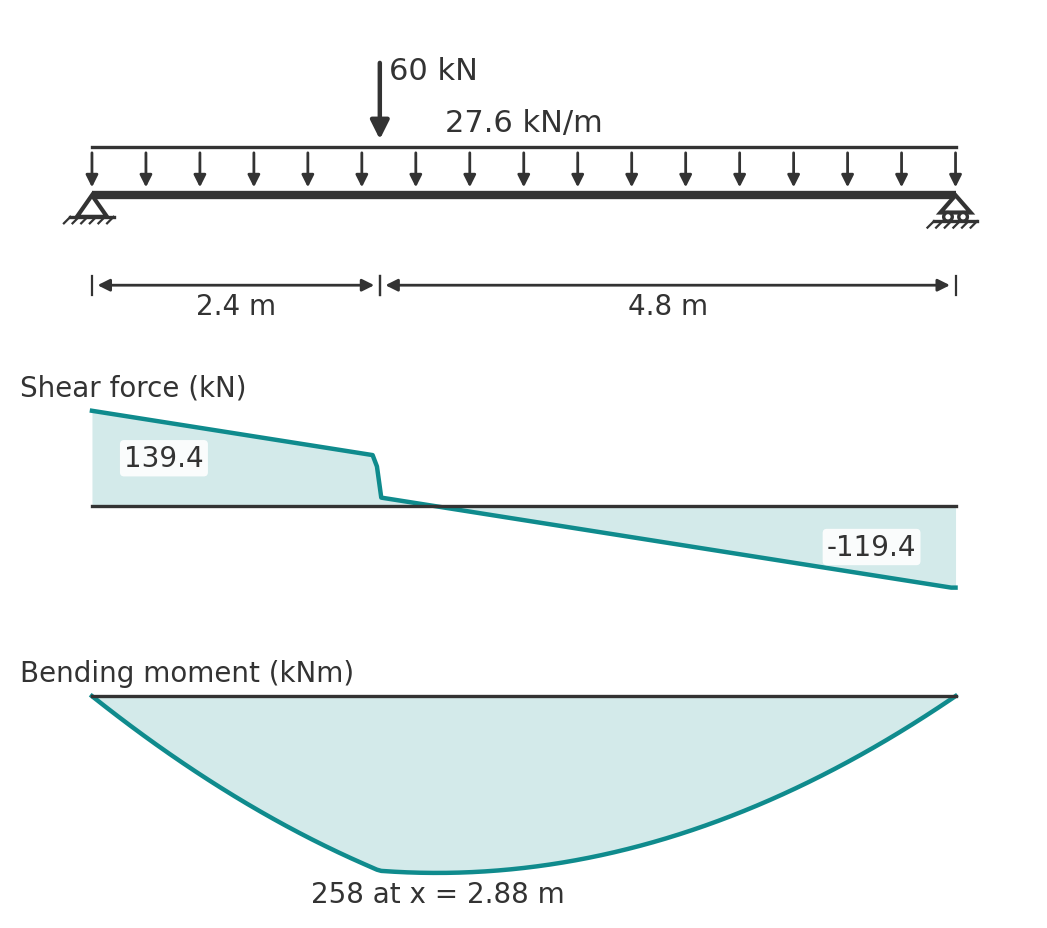
Both examples can be reproduced in the beam analysis pack using Macaulay's theorem, which draws the shear force and bending moment diagrams for a UDL, a point load or both on the same span.
A steel floor beam spans 7.2 m between simple connections. It carries a dead load of \(G = 8\) kN/m (slab, finishes and self-weight) and a live load of \(Q = 12\) kN/m.
Factored load to AS/NZS 1170.0:
$$ w^* = 1.2 \times 8 + 1.5 \times 12 = 27.6 \text{ kN/m} $$
The Eurocode combination gives \(1.35 \times 8 + 1.5 \times 12 = 28.8\) kN/m, about 4 per cent higher. Carrying on with the AS value:
$$ R_A = R_B = \frac{27.6 \times 7.2}{2} = 99.4 \text{ kN} $$
$$ M_{max} = \frac{27.6 \times 7.2^2}{8} = 178.8 \text{ kNm at midspan} $$
The maximum shear is 99.4 kN at each support and the moment is 178.8 kNm at midspan. Those are the two numbers that go into the member check.
Worked example 2: UDL plus a point load
Now a secondary beam frames into the same member 2.4 m from support A, delivering a factored point load of \(P^* = 60\) kN. Work each load separately, then add.
Point load alone, with \(a = 2.4\) m and \(b = 4.8\) m:
$$ R_A = \frac{60 \times 4.8}{7.2} = 40 \text{ kN}, \qquad R_B = \frac{60 \times 2.4}{7.2} = 20 \text{ kN}, \qquad M_{under\ load} = \frac{60 \times 2.4 \times 4.8}{7.2} = 96 \text{ kNm} $$
Combined reactions:
$$ R_A = 99.4 + 40 = 139.4 \text{ kN}, \qquad R_B = 99.4 + 20 = 119.4 \text{ kN} $$
Combined shear just to the right of the point load, at \(x = 2.4\) m:
$$ V = 139.4 - 27.6 \times 2.4 - 60 = 13.1 \text{ kN} $$
The shear is still positive past the load, so the maximum moment is not under the point load. It is where the shear reaches zero:
$$ x_0 = \frac{139.4 - 60}{27.6} = 2.875 \text{ m} $$
$$ M_{max} = 139.4 \times 2.875 - \frac{27.6 \times 2.875^2}{2} - 60 \times \left(2.875 - 2.4\right) = 400.7 - 114.1 - 28.5 = 258.1 \text{ kNm} $$
For comparison, the moment directly under the point load is 255.0 kNm and at midspan 250.9 kNm. Adding the two individual maxima, 178.8 + 96 = 274.8 kNm, would overstate the result by 6 per cent because they occur at different points. Always add the moment functions, not the peaks.
Run it in CalcTree
The beam analysis pack using Macaulay's theorem runs these examples live. Each load case here can be built as a live CalcTree page that draws the shear and moment diagrams from the inputs and carries the peak values straight into a member check. The same pack handles mixed loads by Macaulay's method. For the capacity side, the steel member design to AS 4100 template takes the moment and shear from here.





