
Cantilever beam formulas for reactions, shear force, bending moment and deflection under point, uniform and triangular loads, with two worked examples.
Cantilever beam formulas are short because the structure is simple: one fixed support, one free end, and every load on the beam ends up as shear and moment at the root. This page gives the reaction, shear force, bending moment and deflection formulas for the standard cantilever load cases, explains the sign convention that trips people up, and works through a balcony slab and a steel canopy beam by hand.
Throughout, \(L\) is the cantilever length, \(x\) is measured from the fixed support, hogging moment (tension on top) is negative, and all formulas assume constant \(EI\) and elastic behaviour.
What a cantilever is
A cantilever is a beam supported at one end only. The support is fixed: it stops the beam moving vertically, moving horizontally and rotating. The far end is free to do all three. Because nothing holds the free end up, the fixed support has to provide a moment as well as a vertical reaction, and that moment is the largest in the beam.
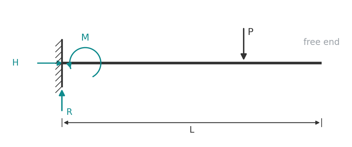
Three reactions (vertical \(R\), horizontal \(H\) and moment \(M\)) against three equations of equilibrium make the cantilever statically determinate. For vertical loads \(H = 0\), the vertical reaction is the total load, and the fixed-end moment is the total load times the distance of its centroid from the support.
Cantilevers are everywhere once you look: balconies and canopies, eaves overhangs, the ends of beams that run past a column, retaining walls and signposts (cantilevered up from a footing), crane runway brackets, and the free-standing columns of a building during erection. A beam that is continuous over a support and extends beyond it behaves as a cantilever on the overhang and transfers the hogging moment back into the span, which is covered on the continuous beam formulas page.
The sign convention
On a simply supported beam the moment sags and the bottom fibre is in tension. On a cantilever the moment hogs: the top fibre is in tension and the bottom in compression. The usual convention writes the cantilever moment as negative to record that. The magnitude is what sizes the section, but the sign matters for detailing. In a reinforced concrete cantilever the main bars go in the top, and a slab that is detailed with bottom bars only will crack at the support and, in the worst case, fall. In a steel cantilever the compression flange is the bottom one, and that is the flange that needs lateral restraint.
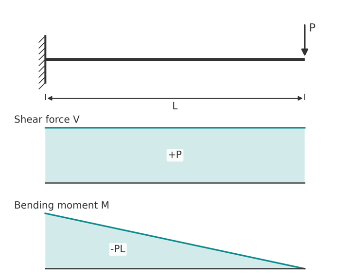
Point load at the free end
$$ R = P, \qquad M_{fixed} = -PL $$
$$ V(x) = P \text{ (constant)}, \qquad M(x) = -P\left(L - x\right) $$
$$ \delta_{tip} = \frac{PL^3}{3EI}, \qquad \theta_{tip} = \frac{PL^2}{2EI} $$
The shear diagram is a rectangle and the moment diagram is a triangle, largest at the support and zero at the tip. Compared with the same load at midspan of a simply supported beam of the same length, the cantilever moment is four times larger and the deflection sixteen times larger.
Uniformly distributed load
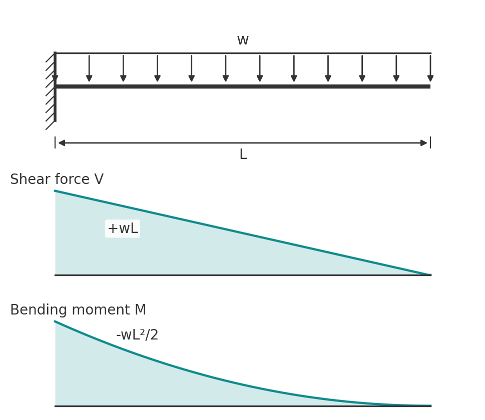
$$ R = wL, \qquad M_{fixed} = -\frac{wL^2}{2} $$
$$ V(x) = w\left(L - x\right), \qquad M(x) = -\frac{w\left(L - x\right)^2}{2} $$
$$ \delta_{tip} = \frac{wL^4}{8EI}, \qquad \theta_{tip} = \frac{wL^3}{6EI} $$
The shear is a straight line from \(wL\) at the support to zero at the tip, and the moment is a parabola with its vertex at the tip. \(wL^2/2\) is four times the simply supported \(wL^2/8\), which is why a cantilever of half the span of its back span carries a comparable moment.
Point load at distance a from the support
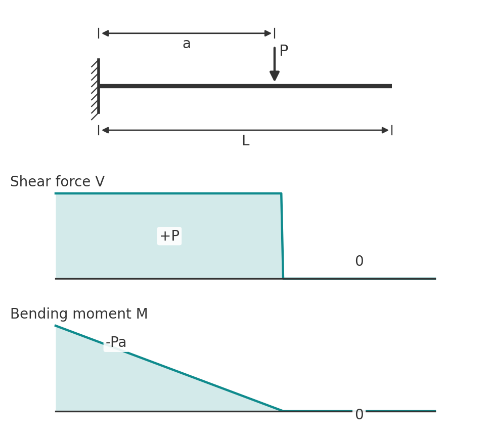
$$ R = P, \qquad M_{fixed} = -Pa $$
$$ V = P \text{ for } x \le a, \; 0 \text{ beyond}, \qquad M(x) = -P\left(a - x\right) \text{ for } x \le a, \; 0 \text{ beyond} $$
$$ \delta_{under\ load} = \frac{Pa^3}{3EI}, \qquad \delta_{tip} = \frac{Pa^2\left(3L - a\right)}{6EI} $$
Beyond the load the beam carries no shear and no moment, but it still deflects because it rotates with the loaded part. The tip deflection is the deflection under the load plus the slope at the load, \(Pa^2/2EI\), times the remaining length \(L - a\).
Partial uniformly distributed load at the free end
For a UDL of \(w\) over a length \(a\) measured from the free end:
$$ R = wa, \qquad M_{fixed} = -wa\left(L - \frac{a}{2}\right) $$
$$ \delta_{tip} = \frac{wa\left(8L^3 - 6aL^2 + a^3\right)}{24EI} $$
With \(a = L\) the moment becomes \(wL^2/2\) and the deflection \(wL^4/8EI\), as it should.
Triangular load
Load increasing from zero at the support to \(w_0\) at the free end:
$$ R = \frac{w_0 L}{2}, \qquad M_{fixed} = -\frac{w_0 L^2}{3}, \qquad \delta_{tip} = \frac{11 w_0 L^4}{120EI} $$
Load of \(w_0\) at the support tapering to zero at the free end:
$$ R = \frac{w_0 L}{2}, \qquad M_{fixed} = -\frac{w_0 L^2}{6}, \qquad \delta_{tip} = \frac{w_0 L^4}{30EI} $$
The reaction is the same in both cases, half the peak intensity times the length. The moment differs by a factor of two because the centroid of the load sits at \(2L/3\) from the support in the first case and \(L/3\) in the second. The second case is the earth pressure on a cantilever retaining wall stem, with the stem treated as a cantilever up from the base.
Moment at the free end
$$ R = 0, \qquad V = 0, \qquad M(x) = M_0 \text{ (constant)}, \qquad \delta_{tip} = \frac{M_0 L^2}{2EI} $$
A moment applied at the tip travels down the cantilever unchanged. This is the case for a cantilever that supports a bracket or a stub column with an eccentric load.
Combining load cases
Because the cantilever is determinate and linear, the cases superpose. A balcony with self-weight as a UDL and a balustrade as a tip load has a root moment of \(wL^2/2 + PL\), a root shear of \(wL + P\) and a tip deflection of \(wL^4/8EI + PL^3/3EI\). Unlike the simply supported beam, every maximum on a cantilever sits at the same place, the fixed support for shear and moment and the free end for deflection, so adding the maxima is exact, not conservative.
Deflection limits for cantilevers
Deflection governs cantilevers more often than strength does, and the limit needs care. Code tables such as AS/NZS 1170.0 Appendix C and the National Annex to EN 1990 express limits as a fraction of span. For a cantilever the common practice is to apply the limit to twice the cantilever length, treating the cantilever as one half of a notional span of \(2L\), so span/250 becomes \(2L/250 = L/125\). Check which convention your project specification uses before sizing the member, and remember that the back span of a continuous beam rotates at the support and adds to the tip deflection. The full set of deflection formulas for other support conditions is on the beam deflection formulas page.
Worked example 1: balcony slab
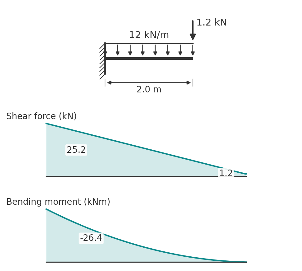
A reinforced concrete balcony cantilevers 2.0 m from the face of the building. Take a 1 m wide strip of slab. The slab and finishes weigh 5.0 kPa, so \(G = 5.0\) kN/m on the strip. Take the live load as \(Q = 4.0\) kPa, giving 4.0 kN/m (check AS/NZS 1170.1 Table 3.1 or EN 1991-1-1 Table 6.2 for the occupancy). A balustrade at the edge adds a dead load of 1.0 kN/m along the edge, which is a tip point load of \(P_G = 1.0\) kN on the strip.
Factored loads to AS/NZS 1170.0 Clause 4.2.2:
$$ w^* = 1.2 \times 5.0 + 1.5 \times 4.0 = 12.0 \text{ kN/m}, \qquad P^* = 1.2 \times 1.0 = 1.2 \text{ kN} $$
Root moment and shear:
$$ M^* = \frac{12.0 \times 2.0^2}{2} + 1.2 \times 2.0 = 24.0 + 2.4 = 26.4 \text{ kNm per metre} $$
$$ V^* = 12.0 \times 2.0 + 1.2 = 25.2 \text{ kN per metre} $$
To EN 1990 Equation 6.10 the loads are \(1.35 \times 5.0 + 1.5 \times 4.0 = 12.75\) kN/m and \(1.35\) kN, giving \(M^* = 28.2\) kNm and \(V^* = 26.9\) kN per metre, about 7 per cent higher. The 26.4 kNm is a hogging moment, so the main reinforcement goes in the top of the slab and must be anchored back into the floor behind the support. That detailing is checked to AS 3600 Section 8 or EN 1992-1-1 Section 6.
Worked example 2: steel canopy beam deflection
The cantilever cases in the beam analysis pack using Macaulay's theorem reproduce this example, with the tip deflection and the fixed-end moment and shear reported together.
A 250UB31.4 cantilevers 3.0 m to carry an entrance canopy. Under serviceability loads it carries \(w = 4.0\) kN/m along its length plus \(P = 10\) kN at the tip from an edge beam. \(E = 200{,}000\) MPa and \(I_x = 44.5 \times 10^6\) mm\(^4\). Working in N and mm:
$$ \delta_P = \frac{PL^3}{3EI} = \frac{10{,}000 \times 3000^3}{3 \times 200{,}000 \times 44.5 \times 10^6} = 10.1 \text{ mm} $$
$$ \delta_w = \frac{wL^4}{8EI} = \frac{4.0 \times 3000^4}{8 \times 200{,}000 \times 44.5 \times 10^6} = 4.6 \text{ mm} $$
$$ \delta_{tip} = 10.1 + 4.6 = 14.7 \text{ mm} $$
Against a limit of \(2L/250 = 24\) mm the beam passes. Against a tighter \(L/180 = 16.7\) mm, which some specifications use for cantilevers with a visible soffit, it still passes but with little margin. The serviceability root moment is \(10 \times 3.0 + 4.0 \times 3.0^2/2 = 48\) kNm, which the strength check picks up after factoring. Note that this ignores the rotation of the beam at its support: if the cantilever is the overhang of a continuous beam, the back span rotation adds to the tip deflection and must be included.
Run it in CalcTree
The beam analysis pack using Macaulay's theorem runs the cantilever cases live. These formulas can be built as a live, checkable CalcTree page, with the cantilever length, loads and section as inputs and the root moment, shear and tip deflection calculated and compared with the limits on the same page. The beam analysis pack using Macaulay's method handles cantilevers with mixed loads, and the steel member design to AS 4100 template takes the moment and shear through to a capacity check. Browse the template library for concrete and timber versions.





