
Beam deflection formulas for simply supported, cantilever, fixed and continuous beams under UDL, point and moment loads, with code limits and a worked example.
Beam deflection formulas give you the maximum vertical movement of a beam under load without solving the differential equation of the elastic curve every time. For the common support conditions and load cases, the answer has already been worked out in closed form, and this page collects the ones you will actually use: simply supported, cantilever, fixed-ended, propped and continuous beams under uniform loads, point loads and end moments.
Every formula below assumes a prismatic beam (constant \(EI\)), linear elastic material, small deflections and bending deformation only. Shear deformation is ignored, which is fine for span-to-depth ratios above about 10. Deflection is a serviceability check, so the loads are unfactored, or factored with the serviceability combinations in the relevant code.
What governs deflection
Every deflection formula has the same shape: a coefficient, a load term, a span term and the flexural rigidity \(EI\) in the denominator.
$$ \delta = C \cdot \frac{w L^4}{EI} \quad \text{or} \quad \delta = C \cdot \frac{P L^3}{EI} $$
where:
\(w\) is a uniformly distributed load (kN/m),
\(P\) is a point load (kN),
\(L\) is the span,
\(E\) is the modulus of elasticity of the material,
\(I\) is the second moment of area of the section about the bending axis, and
\(C\) is a coefficient that depends only on the support conditions and the load arrangement.
Two things follow. Deflection grows with the fourth power of span under distributed load, so a 20 per cent longer span deflects about twice as much. And the section property that matters is \(I\), not area or section modulus, which is why deep sections are so efficient at controlling deflection. If you need \(I\) for a section, see the guide to moment of inertia calculations.
For \(E\), AS 4100 uses 200,000 MPa for structural steel and EN 1993-1-1 Clause 3.2.6 uses 210,000 MPa. Concrete and timber values depend on grade and, for long-term deflection, on creep, so the short-term formulas here are only the starting point for those materials.
Simply supported beam deflection formulas
The beam analysis pack using Macaulay's theorem computes the deflection, slope, shear and moment of a simply supported or cantilever beam under these loads with the working shown.
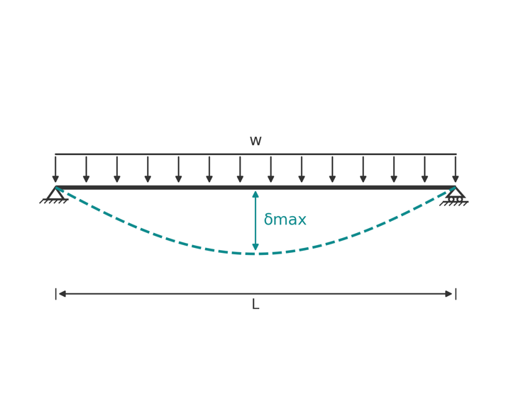
A simply supported beam rests on a pin at one end and a roller at the other. Both ends are free to rotate, so the deflected shape is a single sag between the supports.
Uniformly distributed load
$$ \delta_{max} = \frac{5 w L^4}{384 EI} \quad \text{at midspan}, \qquad \theta_{A} = \theta_{B} = \frac{w L^3}{24 EI} $$
Point load at midspan
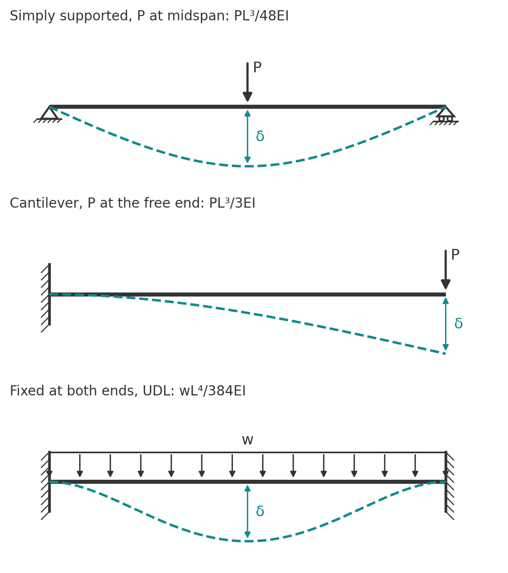
$$ \delta_{max} = \frac{P L^3}{48 EI} \quad \text{at midspan}, \qquad \theta_{A} = \theta_{B} = \frac{P L^2}{16 EI} $$
Point load at any position
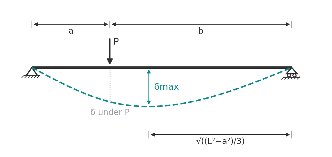
With the load at distance \(a\) from the nearer support and \(b = L - a\) from the other (so \(a \le b\)):
$$ \delta_{under\ load} = \frac{P a^2 b^2}{3 EI L} $$
$$ \delta_{max} = \frac{P a \left(L^2 - a^2\right)^{3/2}}{9\sqrt{3}\, EI L} \quad \text{at } x = \sqrt{\frac{L^2 - a^2}{3}} \text{ from the far support} $$
The maximum deflection is not under the load. It sits between the load and midspan, always within about 8 per cent of the span from the centre, which is why the midspan deflection is often used as a close approximation.
Moment applied at one end
$$ \delta_{max} = \frac{M L^2}{9\sqrt{3}\, EI} \quad \text{at } x = \frac{L}{\sqrt{3}} \text{ from the far end}, \qquad \theta_{near} = \frac{M L}{3 EI}, \quad \theta_{far} = \frac{M L}{6 EI} $$
Two equal point loads, symmetric
With each load at distance \(a\) from its nearest support:
$$ \delta_{max} = \frac{P a \left(3 L^2 - 4 a^2\right)}{24 EI} \quad \text{at midspan} $$
For loads at the third points (\(a = L/3\)) this gives \(23PL^3/648EI\). For loads at the quarter points it gives \(11PL^3/384EI\).
Cantilever beam deflection formulas
A cantilever is fixed at one end and free at the other. The free end always has the largest deflection, and because the fixed support provides the only restraint, cantilevers deflect far more than a simply supported beam of the same length and load.
Point load at the free end
$$ \delta_{tip} = \frac{P L^3}{3 EI}, \qquad \theta_{tip} = \frac{P L^2}{2 EI} $$
Uniformly distributed load
$$ \delta_{tip} = \frac{w L^4}{8 EI}, \qquad \theta_{tip} = \frac{w L^3}{6 EI} $$
Point load at distance a from the fixed end
$$ \delta_{under\ load} = \frac{P a^3}{3 EI}, \qquad \delta_{tip} = \frac{P a^2 \left(3L - a\right)}{6 EI} $$
Beyond the load the beam is unloaded and stays straight, so the tip deflection is the deflection under the load plus the slope there times the remaining length.
Moment at the free end
$$ \delta_{tip} = \frac{M L^2}{2 EI}, \qquad \theta_{tip} = \frac{M L}{EI} $$
Triangular load
For a load that is zero at the fixed end and \(w_0\) at the tip, \(\delta_{tip} = 11 w_0 L^4 / 120 EI\). For the reverse, \(w_0\) at the fixed end tapering to zero at the tip, \(\delta_{tip} = w_0 L^4 / 30 EI\). The full set of moment and shear formulas for these cases is on the cantilever beam formulas page.
Fixed-ended and propped beams
Restraining rotation at the supports cuts deflection sharply. The same load on the same section gives:
- Fixed at both ends, UDL: \(\delta_{max} = wL^4 / 384EI\) at midspan. One fifth of the simply supported value.
- Fixed at both ends, point load at midspan: \(\delta_{max} = PL^3 / 192EI\). One quarter of the simply supported value.
- Propped cantilever (fixed one end, pinned the other), UDL: \(\delta_{max} = wL^4 / 185EI\) at \(0.42L\) from the pinned end.
Real connections are rarely fully fixed. A bolted end plate or a timber joist hanger behaves somewhere between pinned and fixed, so the simply supported value is the safe upper bound unless the connection has been designed and detailed for moment.
Continuous beam deflection formulas
The continuous beam calculator solves the deflected shape of a beam over up to six spans with any mix of UDLs and point loads, which covers the cases below and the unequal-span ones the tables do not.
Continuous beams over several supports are statically indeterminate, so the coefficients below come from solving the full system. They are for equal spans \(L\) and constant \(EI\).
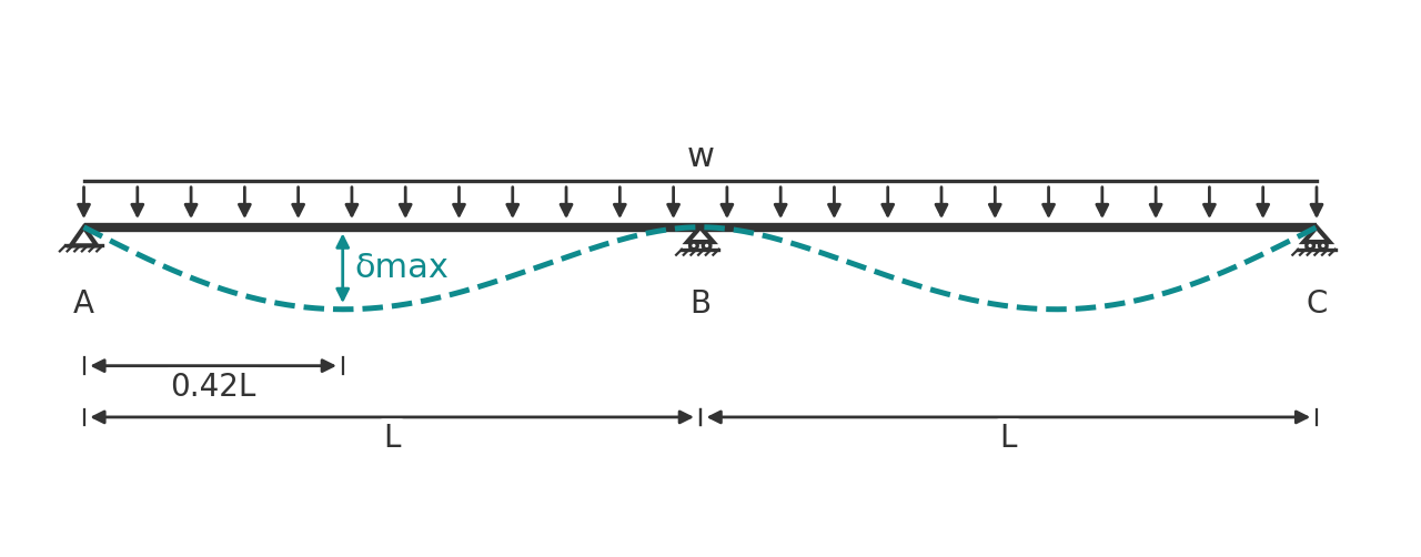
- Two spans, UDL on both: \(\delta_{max} = 0.0054\, wL^4/EI\) (that is \(wL^4/185EI\)) at \(0.42L\) from each end support. By symmetry the centre support behaves like a fixed end, so this matches the propped cantilever.
- Two spans, UDL on one span only: \(\delta_{max} = 0.0092\, wL^4/EI\) at \(0.47L\) from the end support of the loaded span.
- Two spans, point load at the midspan of one span: \(\delta_{max} = 0.0150\, PL^3/EI\) at \(0.48L\) from the end support.
- Three spans, UDL on all spans: \(\delta_{max} = 0.0069\, wL^4/EI\) at \(0.45L\) from the end support, in an outer span.
- Three spans, UDL on the centre span only: \(\delta_{max} = 0.0068\, wL^4/EI\) at the centre of the middle span.
- Three spans, UDL on the two outer spans: \(\delta_{max} = 0.0099\, wL^4/EI\) at \(0.48L\) from the end support.
- Four spans, UDL on all spans: \(\delta_{max} = 0.0065\, wL^4/EI\) at \(0.44L\) from the end support, in an outer span.
Notice that loading one span alone deflects it more than loading every span, because the unloaded neighbour no longer helps to hold the shared support rotation back. For a serviceability check on a continuous beam, the pattern with live load on alternate spans usually governs. The matching moment and reaction coefficients are on the continuous beam formulas page.
Superposition
Because the formulas are linear in load, deflections from different loads on the same beam add directly. A beam carrying self-weight as a UDL plus a point load from a secondary member has a midspan deflection equal to the sum of the two formulas. The only care needed is that the maxima of the individual cases may sit at slightly different points, so adding maxima is marginally conservative. Adding the values at the same point is exact.
Deflection limits in the codes
The codes do not tell you what a beam deflects. They tell you how much is acceptable, and leave the calculation to you.
- Australia and New Zealand: AS/NZS 1170.0 Appendix C gives suggested serviceability limits by element and action, with span/250 to span/500 being typical for floor and roof members depending on the finishes. AS 4100 Appendix B repeats suggested limits for steel members, and AS 3600 Clause 2.3.2 sets limits for concrete members: the same span/250 for total deflection, and span/500 for the deflection after masonry partitions are attached where provision is made for movement (span/1000 where it is not).
- Eurocode: EN 1990 Annex A1.4 sets the serviceability framework and defers the actual limits to the National Annex. EN 1993-1-1 Clause 7.2.1 does the same for steel. EN 1992-1-1 Clause 7.4.1 states span/250 as the general limit for concrete under quasi-permanent load, and span/500 for deflection after construction of elements that could be damaged.
Deflection is checked against serviceability loads, not the factored ultimate loads used for strength. For long-term deflection of concrete and timber, the short-term elastic result is multiplied by a creep factor from the material code, which can double or triple it. See structural load calculations for how the serviceability combinations are built.
Worked example: simply supported steel floor beam
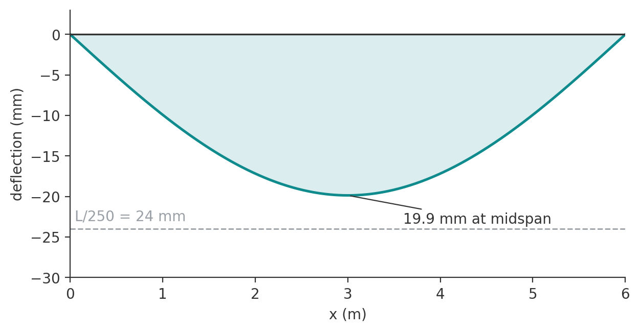
A 310UB40.4 spans 6.0 m between simple supports. Under the serviceability combination it carries \(w = 15\) kN/m along its length plus a 20 kN point load at midspan from a secondary beam. Take \(E = 200{,}000\) MPa and \(I_x = 86.4 \times 10^6\) mm\(^4\). The limit is span/250 for total deflection.
Work in N and mm so the units fall out directly. \(w = 15\) N/mm, \(L = 6000\) mm, \(P = 20{,}000\) N.
$$ \delta_w = \frac{5 w L^4}{384 EI} = \frac{5 \times 15 \times 6000^4}{384 \times 200{,}000 \times 86.4 \times 10^6} = 14.65 \text{ mm} $$
$$ \delta_P = \frac{P L^3}{48 EI} = \frac{20{,}000 \times 6000^3}{48 \times 200{,}000 \times 86.4 \times 10^6} = 5.21 \text{ mm} $$
Both maxima are at midspan, so they add exactly:
$$ \delta_{total} = 14.65 + 5.21 = 19.9 \text{ mm} $$
The limit is \(6000 / 250 = 24\) mm, so the beam passes with about 17 per cent in hand. If a brittle ceiling or masonry partition hung off it and the limit tightened to span/360 (16.7 mm), the same beam would fail the check and need the next section up or a camber. That is the usual pattern: for steel floor beams of ordinary span, deflection rather than bending strength picks the section.
Run it in CalcTree
The beam analysis pack using Macaulay's theorem runs the single-span cases live and the continuous beam calculator the multi-span ones. Each of these formulas can be built as a live CalcTree page, with the span, load and section properties as inputs and the deflection checked against the code limit on the same page. The beam analysis pack using Macaulay's method handles the general case with mixed loads. Browse the template library for material-specific deflection checks.





