
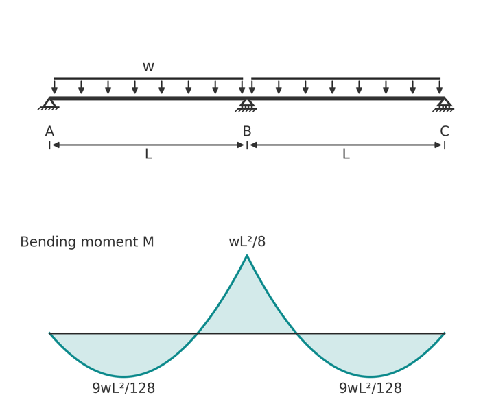
Continuous beam moment formulas and reaction coefficients for two, three and four equal spans under uniform and point loads, with pattern loading and example.
Continuous beam moment formulas are coefficient tables: the support moment is some fraction of \(wL^2\), the span moment is another, and the reactions are fractions of \(wL\). This page collects those coefficients for two, three and four equal spans under uniform and point loads, including the pattern load cases that govern design, and shows how to use them in a hand calculation. Every coefficient here was checked against a stiffness analysis of the beam, so you can use them with confidence.
All formulas assume equal spans \(L\), constant \(EI\), simple supports (pinned at one end, rollers elsewhere) and sagging moment positive. Hogging moments at the supports are quoted as negative.
What a continuous beam is
A continuous beam runs over three or more supports without a break. The beam is one piece, so when one span sags its ends rotate and drag the neighbouring spans with them. That rotation is restrained by the neighbours, which generates a hogging moment over each interior support. The result is a moment diagram that alternates: sagging in the spans, hogging over the supports, with points of contraflexure in between.
Two things follow from the hogging support moments. The span moments are smaller than in a simply supported beam of the same span, which is why continuous construction saves material. And the interior supports carry more than their tributary share of load, which matters for the columns and footings beneath them.
The beam is statically indeterminate. For \(n\) spans there are \(n + 1\) vertical reactions and only two useful equations of equilibrium, so you cannot get the reactions from statics alone. The coefficients below come from solving the compatibility of rotations at the supports, which is what methods like three-moment, moment distribution and stiffness analysis do. If the spans are unequal, the stiffness varies or the supports settle, the coefficients change and you need to run the analysis. Within about 20 per cent variation in span the equal-span values are a reasonable first estimate.
Continuous beams are the norm in cast in-situ concrete, where floor beams run through columns and one-way slabs run over several beams. In steel they appear as continuous purlins and girts with sleeved or overlapping connections (see purlins and girts), crane runway beams, and multi-span bridge girders. Timber floor joists lapped over a bearer are two-span continuous beams.
Two-span continuous beam formulas
Every case on this page, and the unequal-span and mixed-load cases the tables leave out, can be solved in the continuous beam calculator: enter the span lengths, the UDL on each span and any point loads, and read the reactions, support moments and span moments.
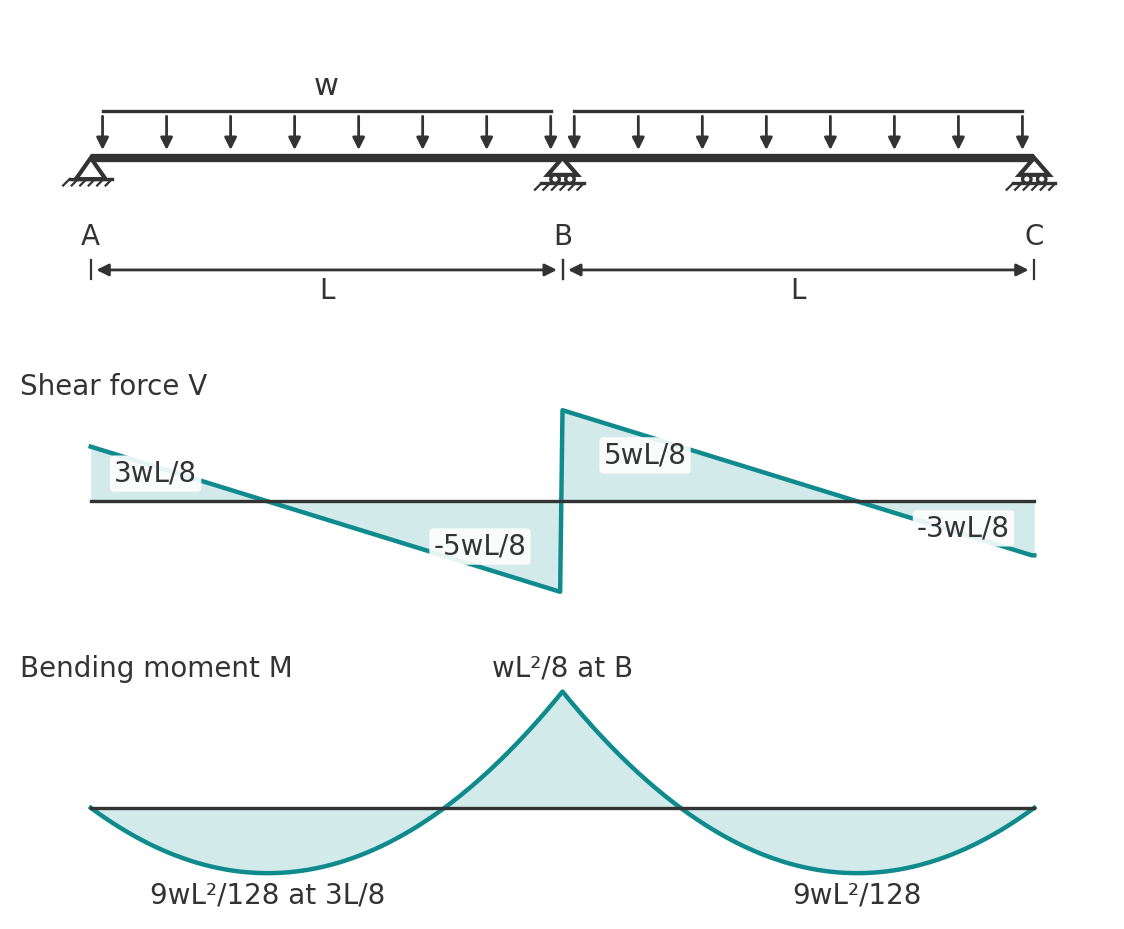
Supports A, B and C with B the interior support. The positions of maximum span moment are measured from the end support.
UDL on both spans
- Support moment: \(M_B = -\dfrac{wL^2}{8} = -0.125\, wL^2\)
- Span moment: \(M_{max} = \dfrac{9wL^2}{128} = 0.070\, wL^2\) at \(x = 3L/8\)
- Reactions: \(R_A = R_C = \dfrac{3wL}{8}\), \(R_B = \dfrac{5wL}{4}\)
- Shear: \(V_A = 3wL/8\), \(V_B = 5wL/8\) on each side of B
The interior support takes 1.25 times its tributary load of \(wL\), and the end supports take only 0.75 of theirs. The support moment is the same \(wL^2/8\) as the midspan moment of a simply supported beam, and the span moment is 44 per cent lower.
UDL on one span only
- Support moment: \(M_B = -\dfrac{wL^2}{16}\)
- Span moment in the loaded span: \(M_{max} = \dfrac{49wL^2}{512} = 0.096\, wL^2\) at \(x = 7L/16\)
- Reactions: \(R_A = \dfrac{7wL}{16}\), \(R_B = \dfrac{5wL}{8}\), \(R_C = -\dfrac{wL}{16}\)
The unloaded span is lifted: \(R_C\) is negative, which means the beam wants to rise off support C. A beam that simply rests on its end support needs holding down, or the analysis must be repeated without that support.
Point load at the midspan of both spans
- Support moment: \(M_B = -\dfrac{3PL}{16}\)
- Span moment: \(M_{max} = \dfrac{5PL}{32}\) under each load
- Reactions: \(R_A = R_C = \dfrac{5P}{16}\), \(R_B = \dfrac{11P}{8}\)
Point load at the midspan of one span
- Support moment: \(M_B = -\dfrac{3PL}{32}\)
- Span moment: \(M_{max} = \dfrac{13PL}{64}\) under the load
- Reactions: \(R_A = \dfrac{13P}{32}\), \(R_B = \dfrac{11P}{16}\), \(R_C = -\dfrac{3P}{32}\)
Three-span continuous beam formulas
Supports A, B, C and D. By symmetry the two outer spans behave alike.
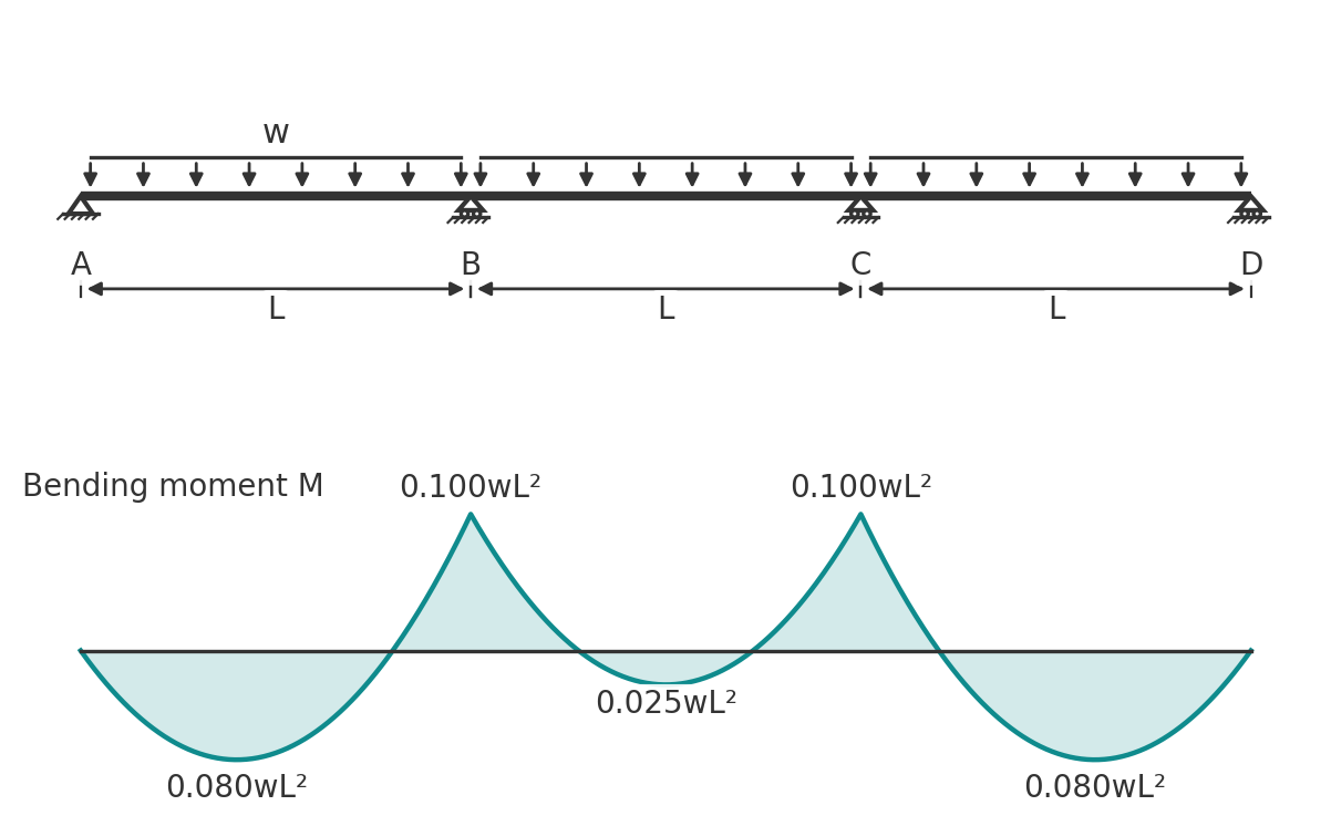
UDL on all spans
- Support moments: \(M_B = M_C = -0.100\, wL^2\)
- Span moments: \(0.080\, wL^2\) in the outer spans at \(x = 0.4L\) from the end support, \(0.025\, wL^2\) at the centre of the middle span
- Reactions: \(R_A = R_D = 0.4\, wL\), \(R_B = R_C = 1.1\, wL\)
- Shear: \(0.6\, wL\) on the outer side of B and C, \(0.5\, wL\) on the inner side
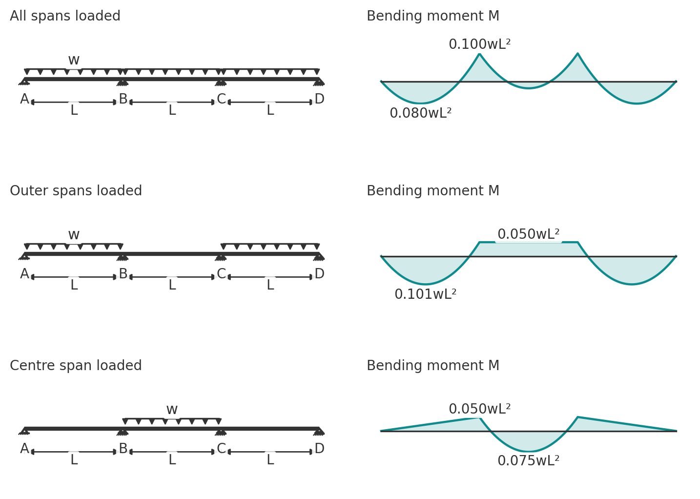
UDL on the two outer spans
- Support moments: \(M_B = M_C = -0.050\, wL^2\)
- Span moment: \(0.101\, wL^2\) at \(x = 0.45L\) from the end support
- Reactions: \(R_A = R_D = 0.45\, wL\), \(R_B = R_C = 0.55\, wL\)
UDL on the centre span only
- Support moments: \(M_B = M_C = -0.050\, wL^2\)
- Span moment: \(0.075\, wL^2\) at the centre of the middle span
- Reactions: \(R_A = R_D = -0.05\, wL\), \(R_B = R_C = 0.55\, wL\)
UDL on two adjacent spans
- Support moments: \(M_B = -0.117\, wL^2\), \(M_C = -0.033\, wL^2\)
- Span moments: \(0.073\, wL^2\) in the end span, \(0.054\, wL^2\) in the middle span
- Reactions: \(R_A = 0.383\, wL\), \(R_B = 1.20\, wL\), \(R_C = 0.45\, wL\), \(R_D = -0.033\, wL\)
Point load at the midspan of every span
- Support moments: \(M_B = M_C = -0.150\, PL\)
- Span moments: \(0.175\, PL\) in the outer spans, \(0.100\, PL\) in the middle span
- Reactions: \(R_A = R_D = 0.35\, P\), \(R_B = R_C = 1.15\, P\)
Pattern loading is the point of the three-span cases. Loading all spans gives the largest support moment. Loading the outer spans only gives the largest outer span moment, 0.101 against 0.080. Loading the centre span only gives the largest centre span moment, 0.075 against 0.025, three times the all-spans value. Loading two adjacent spans gives the largest moment at the shared support, 0.117 against 0.100.
Four-span continuous beam formulas
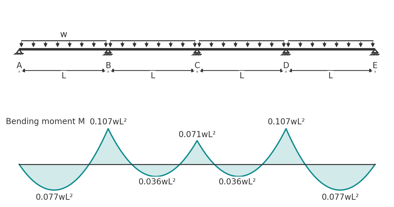
Supports A to E. Spans AB and DE are the outer spans, BC and CD the inner spans.
UDL on all spans
- Support moments: \(M_B = M_D = -0.107\, wL^2\), \(M_C = -0.071\, wL^2\)
- Span moments: \(0.077\, wL^2\) in the outer spans at \(x = 0.39L\), \(0.036\, wL^2\) in the inner spans
- Reactions: \(R_A = R_E = 0.393\, wL\), \(R_B = R_D = 1.143\, wL\), \(R_C = 0.929\, wL\)
UDL on the first and third spans
- Support moments: \(M_B = M_D = -0.054\, wL^2\), \(M_C = -0.036\, wL^2\)
- Span moments: \(0.100\, wL^2\) in the first span at \(x = 0.45L\), \(0.081\, wL^2\) in the third span
- Reactions: \(R_A = 0.446\, wL\), \(R_B = 0.571\, wL\), \(R_C = 0.464\, wL\), \(R_D = 0.571\, wL\), \(R_E = -0.054\, wL\)
UDL on the two centre spans
- Support moments: \(M_B = M_D = -0.036\, wL^2\), \(M_C = -0.107\, wL^2\)
- Span moments: \(0.056\, wL^2\) in each loaded span
- Reactions: \(R_A = R_E = -0.036\, wL\), \(R_B = R_D = 0.464\, wL\), \(R_C = 1.143\, wL\)
Beyond four spans the coefficients barely change. The first interior support moment settles at about \(0.105\, wL^2\) and the remaining interior supports at about \(0.079\, wL^2\), with end span moments near \(0.078\, wL^2\). For long runs of equal spans the five-span values are close enough for any number of spans.
Pattern loading and the design envelope
Dead load is always present on every span, but live load can be anywhere. To design a continuous beam you need the worst case at every section, which means combining the coefficients for several load arrangements:
- Maximum sagging in a span: dead load on all spans, live load on that span and on alternate spans either side.
- Maximum hogging at a support: dead load on all spans, live load on the two spans adjacent to that support and on alternate spans beyond.
- Maximum reaction or shear at a support: the same arrangement as maximum hogging.
EN 1992-1-1 Clause 5.1.3 sets out the load arrangements to consider for buildings, and AS 3600 requires the imposed action to be arranged for the most adverse effect. The envelope is then the outer bound of all the moment diagrams. Because live load on alternate spans unloads the support, the hogging moment under pattern loading is smaller than under full loading, but the sagging moment is larger. Both cases must be checked, and the span usually needs more bottom reinforcement or a larger section than the all-spans case alone would suggest.
Code simplifications and redistribution
For concrete beams and one-way slabs of roughly equal span under uniform load, the codes offer short cuts. AS 3600 Clause 6.10.2 gives a simplified method with moment coefficients that already allow for pattern loading, and ACI 318-19 Clause 6.5 gives its well-known approximate moments and shears, which CalcTree has as a live template. Eurocode 2 has no coefficient table in the main text and expects an elastic analysis. All three permit the elastic support moments to be redistributed to the spans within limits (AS 3600 Clause 6.2.7, EN 1992-1-1 Clause 5.5), which is a useful way of relieving congested reinforcement over a support. Note that the coefficients on this page are elastic, unredistributed values, and for the simplified code methods the span is usually the clear span rather than the centre-to-centre span used here.
Deflection coefficients for the same cases are on the beam deflection formulas page.
Worked example: two-span floor beam
The continuous beam calculator reproduces this example: two spans of 6 m with the factored UDL on each, then the live load on one span only for the pattern case.
A floor beam is continuous over two equal spans of 6.0 m. It carries a dead load of \(G = 10\) kN/m and a live load of \(Q = 12\) kN/m. Factored to AS/NZS 1170.0 Clause 4.2.2, the full load is \(w^* = 1.2 \times 10 + 1.5 \times 12 = 30\) kN/m, the dead load alone is \(1.2 \times 10 = 12\) kN/m, and the live load alone is \(1.5 \times 12 = 18\) kN/m. EN 1990 Equation 6.10 would give 31.5 kN/m in place of 30.
Case 1: full load on both spans
$$ M_B = -\frac{30 \times 6.0^2}{8} = -135 \text{ kNm} $$
$$ M_{span} = \frac{9 \times 30 \times 6.0^2}{128} = 75.9 \text{ kNm at } 2.25 \text{ m from A} $$
$$ R_A = R_C = \frac{3 \times 30 \times 6.0}{8} = 67.5 \text{ kN}, \qquad R_B = \frac{5 \times 30 \times 6.0}{4} = 225 \text{ kN}, \qquad V_B = \frac{5 \times 30 \times 6.0}{8} = 112.5 \text{ kN} $$
Case 2: dead load on both spans, live load on span AB only
Superpose the both-spans coefficients for the 12 kN/m dead load and the one-span coefficients for the 18 kN/m live load.
$$ M_B = -\frac{12 \times 36}{8} - \frac{18 \times 36}{16} = -54.0 - 40.5 = -94.5 \text{ kNm} $$
$$ M_{span} \approx \frac{9 \times 12 \times 36}{128} + \frac{49 \times 18 \times 36}{512} = 30.4 + 62.0 = 92.4 \text{ kNm} $$
The span value is an upper bound because the two peaks sit at 2.25 m and 2.63 m. Adding the moment functions rather than the peaks gives 91.9 kNm at 2.48 m, so the difference is under 1 per cent and the quick sum is fine for design.
$$ R_A = \frac{3 \times 12 \times 6.0}{8} + \frac{7 \times 18 \times 6.0}{16} = 27.0 + 47.3 = 74.3 \text{ kN} $$
$$ R_C = 27.0 - \frac{18 \times 6.0}{16} = 27.0 - 6.75 = 20.3 \text{ kN} $$
$$ R_B = 1.25 \times 12 \times 6.0 + \frac{5 \times 18 \times 6.0}{8} = 90.0 + 67.5 = 157.5 \text{ kN} $$
Design values
The design hogging moment is 135 kNm from case 1. The design sagging moment is 92 kNm from case 2, 21 per cent higher than the 75.9 kNm you would get by loading everything at once. The column under B is designed for 225 kN from case 1, and support C stays in compression under case 2 (20.3 kN), so no hold-down is needed. The equivalent simply supported beam would need to carry 135 kNm in every span, so continuity has cut the span moment by about a third while concentrating the load on the central column.
Run it in CalcTree
The continuous beam calculator runs this example live, including the pattern-load case. A continuous beam with its load patterns is exactly the kind of calculation that benefits from being a live, checkable CalcTree page: change a span or a load and every coefficient, envelope and reaction updates together. The ACI 318-19 approximate moments and shears template covers the code simplified method, and the beam analysis pack using Macaulay's method handles general load cases. Browse the template library for concrete beam design to AS 3600 and Eurocode 2.





