Calculate factored Mu and Vu for continuous beams and one-way slabs using ACI 318-19 Cl. 6.5. Run this free template on CalcTree.

This template is not available yet. You can sign up and create it yourself!
Or let us know if you'd like to be notified when it’s ready:
No items found.
No items found.
About this ACI 318-19: Approximate Moments and Shears - Nonprestressed Continuous Beams and One-Way Slabs (Cl. 6.5) Calculator
This calculator estimates factored moments and factored shears due to gravity loads for nonprestressed continuous beams and one-way slabs using the ACI 318-19 Cl. 6.5 simplified method. It checks all five applicability conditions under Cl. 6.5.1(a–e), then applies the appropriate moment coefficients from Table 6.5.2 and shear coefficients from Table 6.5.4 based on span location, end condition, support type, and number of spans.
- Structural engineer — verify applicability of the simplified method and extract design-governing factored moments and shears for continuous beam or slab spans without running a full frame analysis.
- Concrete designer — select the correct coefficient for each span and support condition, confirm moment redistribution is not applied per Cl. 6.5.3, and carry results directly into flexural and shear design.
- Plan checker or reviewer — audit the applicability checks and coefficient selection against the code tables in a single traceable calculation.
This is an engineering-grade calculator built on CalcTree, where every applicability flag, coefficient, and result is fully visible and auditable within your project workspace.
More info on ACI 318-19: Approximate Moments and Shears - Nonprestressed Continuous Beams and One-Way Slabs (Cl. 6.5)
Applicability Checks (Cl. 6.5.1)
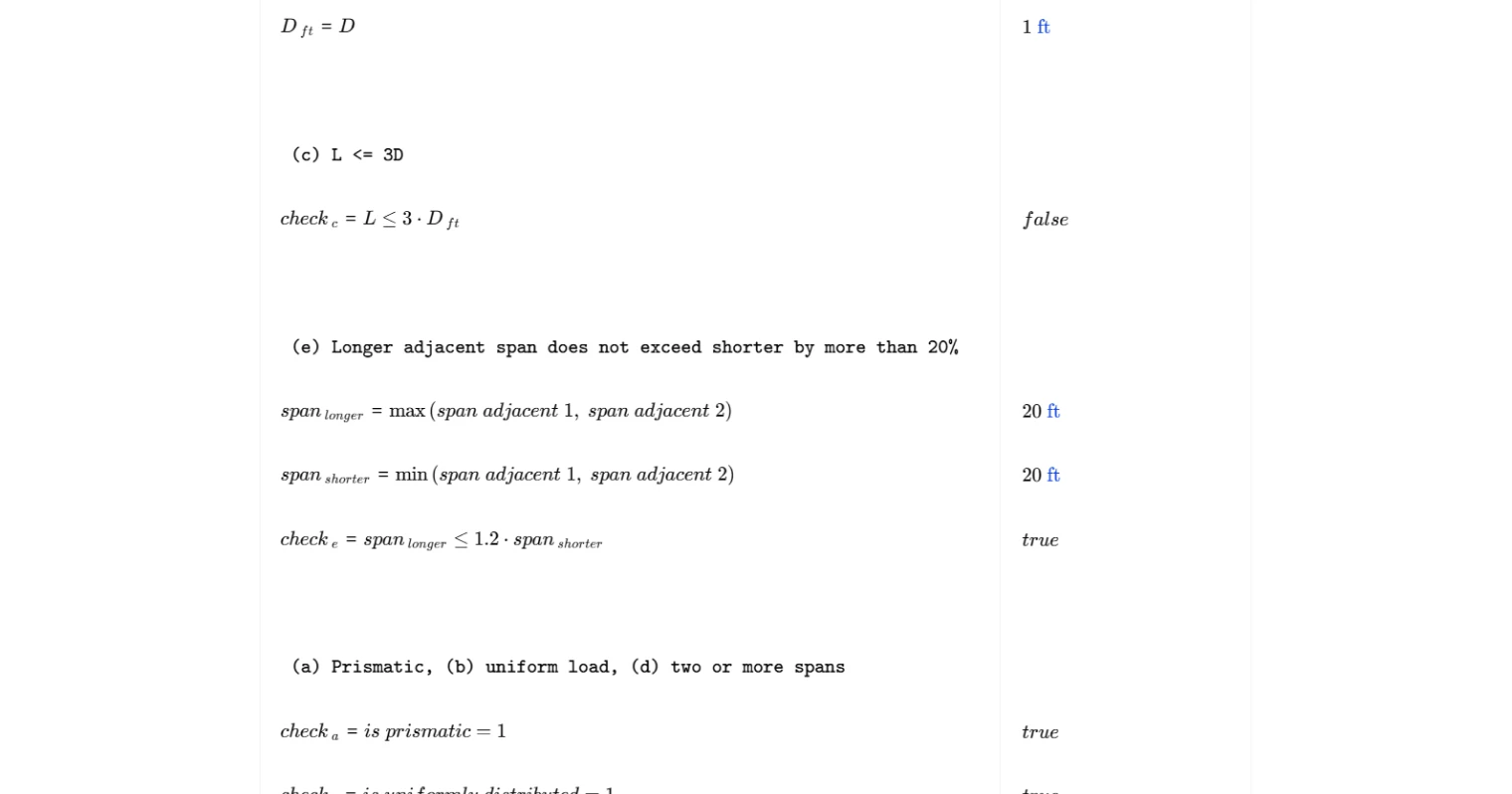
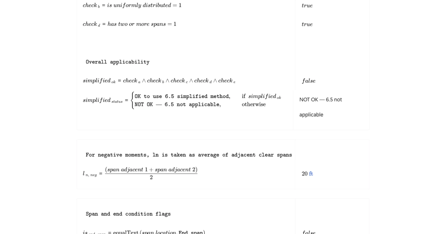
Before any moments or shears are computed, the calculator evaluates all five conditions required by Cl. 6.5.1. These checks confirm that the member is prismatic, the applied load is uniformly distributed, the ratio of live load to dead load is within the permitted limit, the structure has two or more spans, and adjacent clear spans do not differ by more than 20%. Each condition is assessed independently using user-supplied geometry and load flags, and the overall applicability status is reported as a pass or fail. If any condition is not met, the simplified method is not valid and a more rigorous analysis is required.
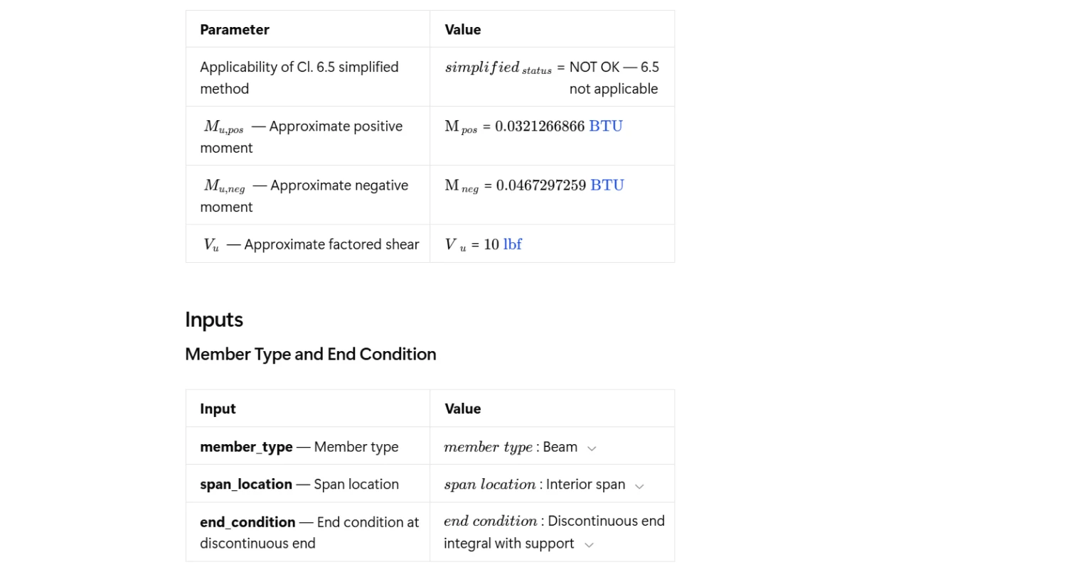
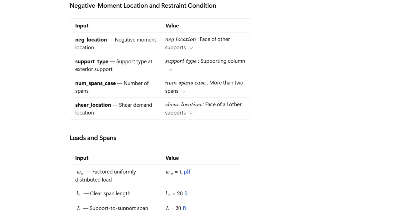
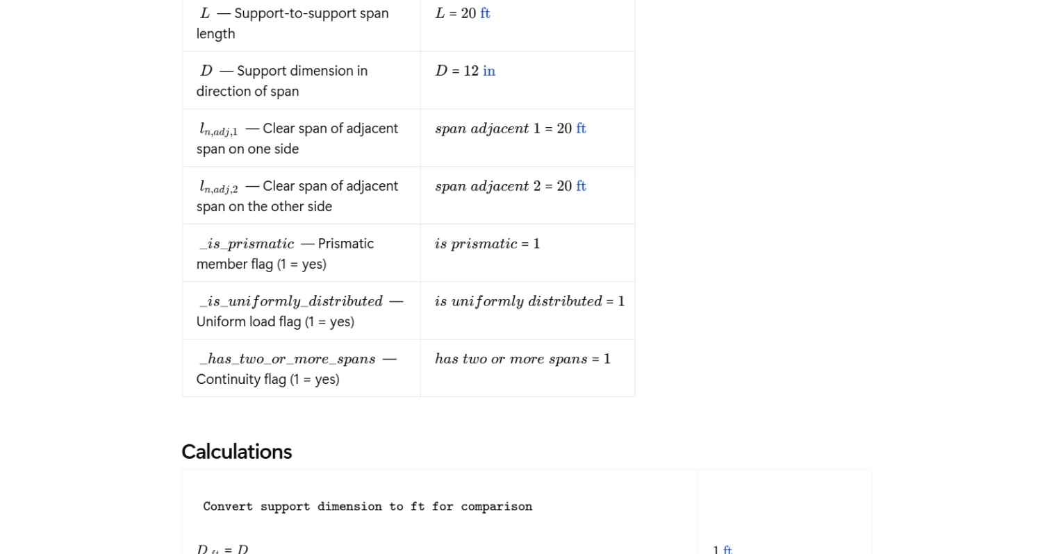
Inputs
The calculator takes in member type and span configuration through dropdown selections covering beam or one-way slab, end span or interior span, and the end condition at the discontinuous end. Additional selections define the negative-moment location, exterior support type, number of spans, and shear demand location. Geometric inputs include the clear span length, the support-to-support span length, the support dimension in the direction of span, and the clear spans of adjacent spans on each side. The factored uniformly distributed load is entered directly, along with flags confirming whether the member is prismatic, the load is uniformly distributed, and the structure has two or more spans.
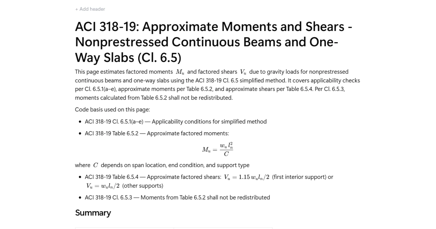
Approximate Moments (Table 6.5.2)
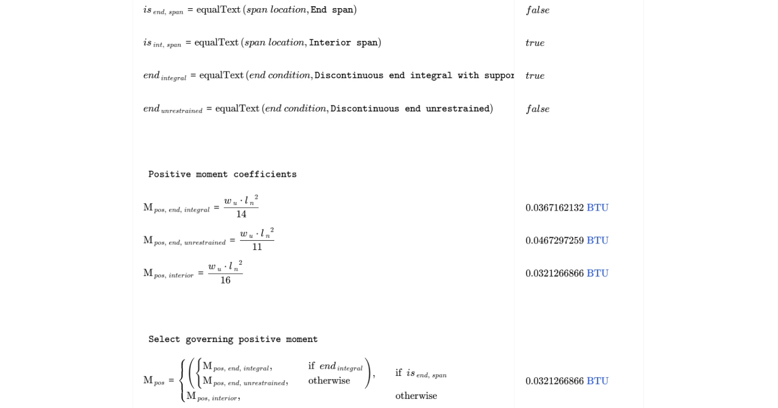
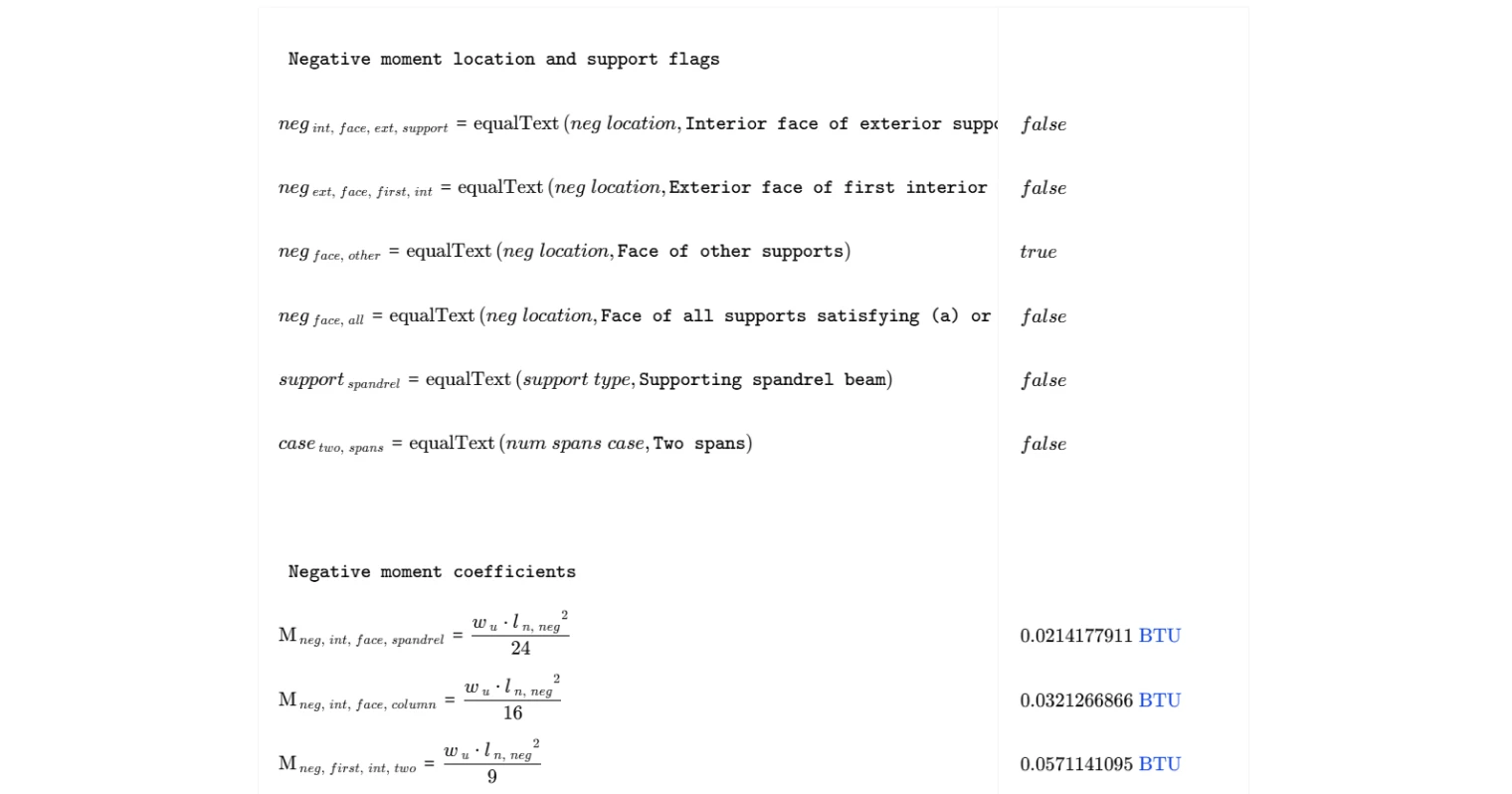
Positive moments are calculated using the expression $M_u = w_u l_n^2 / C$, where the coefficient $C$ is selected based on span location and end condition. End spans with a discontinuous end integral with the support use a different coefficient than those with an unrestrained discontinuous end, while interior spans use a separate coefficient. For negative moments, the clear span used in the formula is taken as the average of the two adjacent clear spans, consistent with the Table 6.5.2 note. The negative-moment coefficient depends on the location relative to supports, the type of exterior support, and whether the structure has two spans or more than two spans. Per Cl. 6.5.3, moments derived from these coefficients shall not be redistributed.
Approximate Shears (Table 6.5.4) and Outputs
Factored shear is calculated based on the selected shear demand location. At the exterior face of the first interior support, a 15% amplification is applied to account for pattern loading effects, giving $V_u = 1.15 , w_u l_n / 2$. At all other supports, $V_u = w_u l_n / 2$. The summary table reports the applicability status, the governing positive moment, the governing negative moment, and the governing factored shear, giving a concise set of results ready for use in flexural and shear design.
Common Calculation Errors to Avoid
- Skipping the applicability checks — using the Cl. 6.5 method without verifying all five conditions under Cl. 6.5.1 can produce unconservative results; the method is only valid when all checks pass.
- Using the wrong clear span for negative moments — negative moments must use the average of the two adjacent clear spans, not the clear span of the span being designed; confusing these two values leads to incorrect moment demand.
- Misidentifying the span location or end condition — selecting interior span when the span is actually an end span, or choosing the wrong end condition, will apply the wrong coefficient and produce an incorrect moment.
- Applying moment redistribution — Cl. 6.5.3 explicitly prohibits redistribution of moments calculated from Table 6.5.2; redistributing these results violates the code and invalidates the simplified approach.
- Mixing up support types at the exterior support — the negative moment coefficient at the interior face of an exterior support differs depending on whether a spandrel beam or a column provides restraint; using the wrong support type misrepresents the actual boundary condition.
- Using the amplified shear coefficient at the wrong location — the 1.15 factor applies only at the exterior face of the first interior support; applying it at other supports overstates shear demand and wastes section capacity.
- Entering support-to-support span length in place of clear span — the coefficient method uses the clear span $l_n$, not the centre-to-centre span; substituting the wrong length will overestimate moments and shears.
Engineering templates
Common calculators
Design guides
FAQs
What is the ACI 318-19 Cl. 6.5 simplified method and when does it apply?
The Cl. 6.5 simplified method provides approximate factored moments and shears for nonprestressed continuous beams and one-way slabs under gravity loads, without requiring a full elastic analysis. It applies only when all five conditions in Cl. 6.5.1 are satisfied: the member is prismatic (a), loads are uniformly distributed (b), live load does not exceed three times dead load (c), there are two or more spans (d), and adjacent spans differ by no more than 20% (e). The calculation checks these conditions automatically and flags whether the method is applicable before returning results.
What does the 1.15 factor in the shear equation mean?
The 1.15 multiplier on wu·ln/2 at the exterior face of the first interior support accounts for pattern loading effects. Because the first interior support attracts higher shear than other interior supports under unequal loading patterns, ACI increases the shear demand by 15% at that location. At all other supports, the standard value of wu·ln/2 applies. Select the correct shear location in the dropdown to get the right result.
Why does the negative moment use an averaged clear span instead of the actual span?
Per ACI 318-19 Table 6.5.2, the clear span used to compute negative moments at interior supports is taken as the average of the two adjacent clear spans. This accounts for the fact that the negative moment region is influenced by loading on both sides of the support. The calculator computes this average automatically from the two adjacent span inputs and applies it only to the negative moment calculation.
Can I redistribute the moments calculated by this method?
No. ACI 318-19 Cl. 6.5.3 explicitly prohibits redistribution of moments obtained from Table 6.5.2. This is a hard code restriction, not an engineering judgment call. If moment redistribution is needed, run a full elastic analysis under Cl. 6.8 instead and apply the redistribution rules from Cl. 6.6.5.
How do I choose the right coefficient C for my situation?
The coefficient C in Mu = wu·ln²/C depends on three things: whether the span is an end span or interior span, the end condition at the discontinuous end (unrestrained vs. integral with support), and the negative moment location and support type. The dropdowns in the template map directly to the rows in Table 6.5.2. Select each one carefully — an end span with an unrestrained discontinuous end uses C = 11, while an integral end condition uses C = 14, and interior spans always use C = 16.
What inputs do I need to check the five applicability conditions?
You need a prismatic member flag, a uniform load flag, a two-or-more-spans flag, the support-to-support span length L, the support dimension D in the span direction, and the clear spans of both adjacent spans. The ratio check L ≤ 3D covers Cl. 6.5.1(c), and the adjacent span check covers Cl. 6.5.1(e). The three binary flags cover conditions (a), (b), and (d). All five are evaluated simultaneously, and the applicability status is shown before the moment and shear results.
Learn about the benefits of using CalcTree on engineering projects!