Free Timber Beam Design Tool to AS 1720.1:2010. Step-by-step, engineering-grade tool with downloadable report.

This template is not available yet. You can sign up and create it yourself!
Or let us know if you'd like to be notified when it’s ready:
No items found.
No items found.
About this Timber Beam Design to AS 1720.1-2010 Calculator
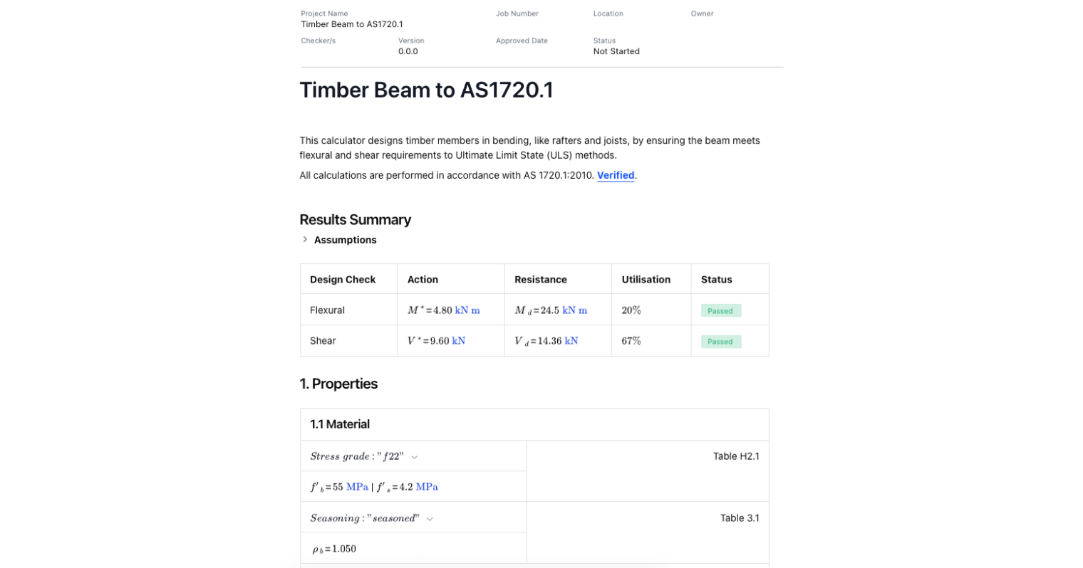
Timber design calculations are a growing trend, and this calculator streamlines timber beam design to AS 1720.1:2010. This tool assists engineers and designers in efficiently selecting and verifying timber members subjected to bending, such as rafters and joists. Using the Ultimate Limit State (ULS) methods, this tool ensures that your timber beams meet the necessary flexural and shear requirements, as specified in the AS 1720.1:2010 standard.
- Structural engineers: use it to verify timber sections, check bending capacity, and confirm compliance with AS 1720.1.
- Architects: quickly check section sizing when specifying timber beams in residential and commercial buildings.
- Builders and contractors: cross-check spans and loading requirements before installation.
The calculator includes a built-in guide that walks users through each step of the timber beam design process for any beam design project. Users can choose from default values or customize parameters based on their project needs. For more detailed guidance on timber design standards, please see: Timber Design: Australian Standards AS1720 and AS1684.
Introduction to Timber Beam Design Calculations
Understanding Loads and Limit States
Designing timber beams involves accounting for vertical loads such as dead load, live load, and wind load. AS 1720.1:2010 uses capacity reduction factor provisions to ensure safe design under ultimate limit states, with serviceability checks to control deflection limits.
Bending and Shear Checks
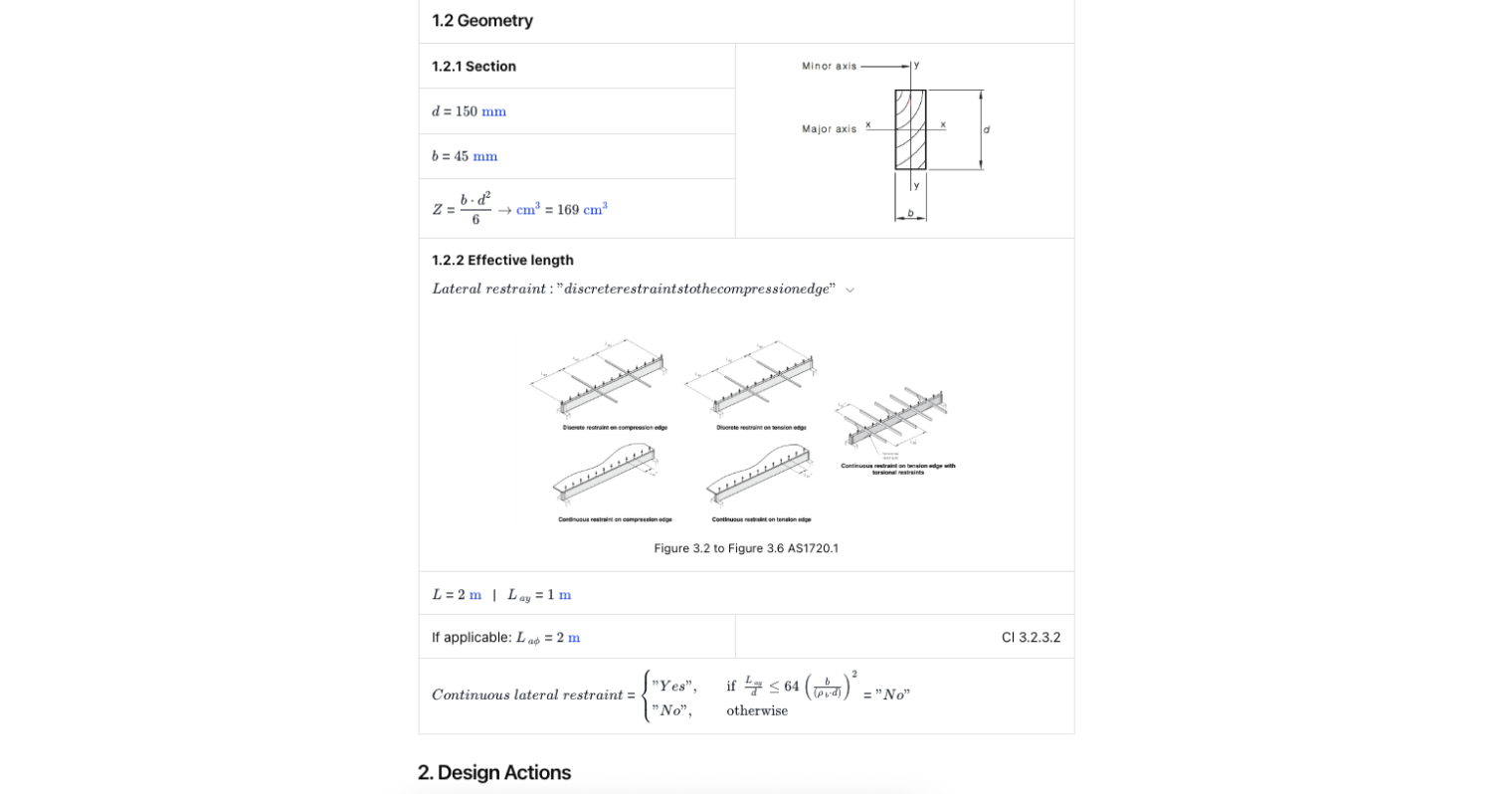
A beam’s bending moment and bending capacity must be checked against the applied loads. Checks along the minor axis are also important for lateral stability in timber beam design, as the minor axis influences buckling behavior and is used to determine the effective length for stability assessments. While reinforced concrete beams rely on a stress block and steel reinforcement to handle tensile stresses, timber beams rely on their material properties and section modulus. Engineers still prepare a bending moment diagram to confirm loading paths.
Deflection and Serviceability
Even when bending strength is sufficient, excessive deflection can make a beam unsuitable. Timber beam design considers simplified method checks to ensure the cross section stays within deflection limits under long-term loading.
Comparing Timber to Other Materials
Timber design uses different principles than concrete beam design or steel beams. Reinforced concrete beams use shear reinforcement, longitudinal reinforcement, and stirrup spacing to handle shear forces and flexural and shear reinforcement to boost performance. Timber beams depend entirely on member sizing, grade, and span to achieve strength. This means that, in the context of structural design, the load-carrying capacity and performance of timber beams are determined by these specific factors rather than by additional reinforcement methods.
Timber Properties and Modification Factors
The performance of any timber structure begins with a thorough understanding of timber’s material properties. These properties—such as strength, stiffness, and durability—are fundamental to how timber elements behave under load and are central to safe, high-quality construction. Australian Standards set out minimum requirements and guidelines for these material characteristics, ensuring that timber used in structural applications meets the demands of modern building codes.
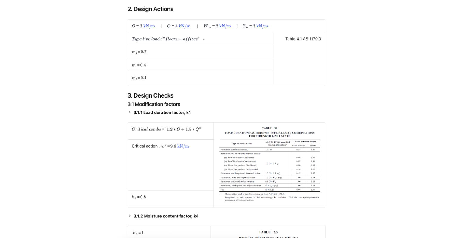
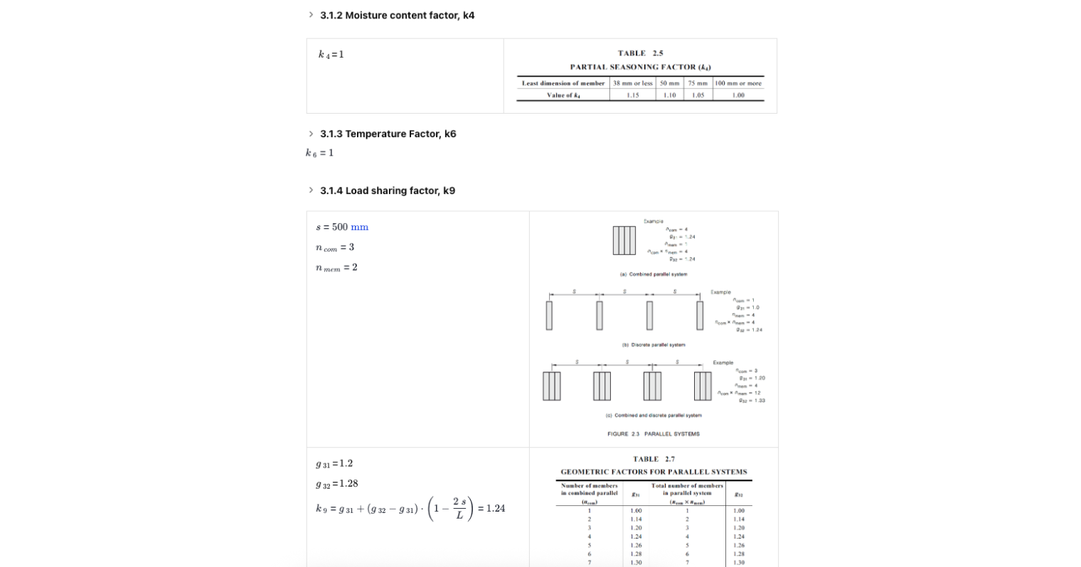
One of the most important aspects of timber design is the use of modification factors. These factors adjust the design capacity of timber members to account for real-world conditions that can cause timber strength to vary. For example, the load duration factor reflects how timber’s strength changes depending on whether loads are short-term (like wind or imposed loads) or long-term (such as the weight of the structure itself). Other modification factors may account for moisture content, temperature, or the specific application of the timber element.
Architects and engineers must be aware of these factors and apply them correctly to ensure the safety and excellence of timber structures. By considering how material properties and modification factors interact, professionals can design timber elements that are not only strong and reliable but also optimized for their intended applications.
Geometric Properties and Calculation
The geometric properties of a timber element—its size, shape, and cross-sectional dimensions—play a crucial role in determining its structural performance. For each type of action, whether it’s compression, tension, or bending, specific geometric properties must be considered in the design calculations.
For example, a timber beam subjected to bending will require a section size with sufficient depth and width to achieve the necessary bending strength and resist shear forces. In compression members, such as columns, the cross-sectional area and slenderness ratio are key factors in preventing buckling and ensuring adequate load-carrying capacity. The choice of section size can also affect the need for additional supports or reinforcement; a larger section may increase strength and stiffness, while a smaller section might require closer spacing or supplementary elements.
Engineers must carefully evaluate these geometric properties for each timber element to ensure the structure can perform safely and efficiently under all expected loads. By selecting the right section size and shape, designers can optimize timber structures for both strength and cost, while meeting the requirements of the building code.
Stability and Bearing Capacity
Ensuring the stability and bearing capacity of timber elements is essential for the safety and longevity of any timber structure. Stability refers to the ability of a timber element, such as a column or beam, to resist buckling or lateral movement under load. Bearing capacity, meanwhile, is the maximum load a timber element can support at points of contact, such as where a beam rests on a support.
The calculation includes Australian Standard's clear guidelines for calculating both stability and bearing capacity, including the use of capacity factors and modification factors. For instance, increasing the section size of a timber column or providing additional lateral restraint can significantly increase its capacity factor, allowing it to safely support greater imposed loads, including those from snow or wind. These considerations are especially important in regions where environmental loads can vary widely.
Engineers must assess each timber element for stability and bearing capacity, taking into account the specific application, location, and loading conditions. By doing so, they ensure that timber structures remain safe, reliable, and compliant with all relevant codes and standards.
Want to learn more before using this template, see: Timber Design: Australian Standards AS1720 and AS1684.
Common Calculation Errors to Avoid
- Mixing material assumptions: Timber design isn’t the same as reinforced concrete design. Relying on concrete beam rules like minimum shear reinforcement or steel reinforcement calculations can lead to unsafe results.
- Ignoring cross section checks: Engineers sometimes skip verifying that the cross section is adequate for both bending capacity and shear forces. Even though timber doesn’t use a rectangular stress block or equivalent rectangular stress block, the same engineering rigor applies.
- Forgetting serviceability: Oversights on deflection limits are common. Timber beams can sag significantly if not checked under the simplified method.
- Applying reinforced concrete terminology incorrectly: Terms like neutral axis, concrete crushes, or concrete cover belong to reinforced concrete structures and reinforced concrete elements. These do not directly translate to timber, though comparisons can help clarify concepts.
- Missing the impact of stirrup spacing analogies: Some engineers mistakenly apply reinforced concrete beam design ideas like stirrup spacing or minimum steel to timber, leading to confusion when designing reinforced concrete beams alongside timber members.
Engineering templates
Common calculators
Design guides
FAQs
What is the difference between timber and reinforced concrete beam design?
Timber beam design relies on the strength of the timber itself. Reinforced concrete beams combine concrete and steel reinforcement, relying on a rectangular stress block to resist compressive loads and reinforcement ratio to handle tensile stresses.
Do timber beams need shear reinforcement like concrete beams?
No. Timber beams don’t use shear reinforcement area checks or minimum shear reinforcement like reinforced concrete beams. Shear forces are resisted by the timber section itself.
Can I use the simplified method for every timber beam?
The simplified method in AS 1720.1-2010 works for most domestic and light commercial spans, but for unusual cross sectional shapes or high vertical loads, a detailed method may be required.
Does timber beam design involve a neutral axis?
Yes, though not in the same way as concrete. A neutral axis still exists in any beam cross section where tensile stresses and compressive stresses change, but timber doesn’t use the same stress block approach seen in reinforced concrete beam design.
Summary and References
This Timber Beam Design to AS 1720.1-2010 design tool simplifies sizing beams for bending capacity, deflection limits, and serviceability, without the need for flexural and shear reinforcement or concrete shear strength checks. While reinforced concrete beams involve concepts like stress block, concrete cover, minimum steel, and stirrup spacing, timber beam design focuses on section properties, grade, and loading.
For related resources, see:
- Timber Design: Australian Standards AS1720 and AS1684
- AS 1720.1-2010 standard for Australian timber design


Learn about the benefits of using CalcTree on engineering projects!