
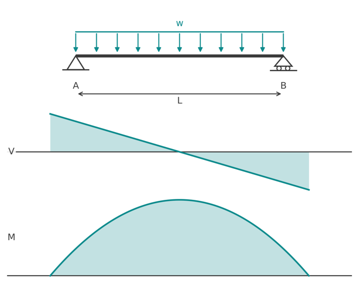
How to calculate shear force and bending moment along a beam, draw the diagrams and check them, with worked examples and AS 4100 and Eurocode references.
Shear force and bending moment diagrams show how the internal actions in a beam change along its length. Every beam design starts with them: the peak values they reveal are the design actions the section has to resist, and their shape tells you where the top is in tension, where to curtail bars or splice flanges, and where the deflection will be largest.
This guide covers what the internal forces are, the sign convention, the relationships between load, shear and moment, a repeatable procedure for drawing the diagrams, and three worked examples checked by hand.
What the internal forces are
Cut a loaded beam at any point and the two halves would separate unless something held them together. That something is the set of internal actions at the cut: an axial force \( N \) along the beam, a shear force \( V \) across it, and a bending moment \( M \) that stops the two halves rotating relative to each other. For a beam carrying transverse loads, \( N \) is usually zero and the design is governed by \( V \) and \( M \).
The shear force at a section is the resultant of all the transverse forces on one side of the cut. The bending moment at a section is the sum of the moments of all the forces on one side of the cut, taken about the section. Either side gives the same answer, so pick the side with fewer loads on it.

Sign convention
- Shear is positive when the resultant of the forces to the left of the cut acts upward. Equivalently, positive shear pushes the left part up and the right part down.
- Bending moment is positive when it causes sagging: compression in the top fibre and tension in the bottom. Hogging moments, which put the top in tension, are negative.
- Axial force is positive in tension.
Sagging-positive is the convention used in most Australian and European textbooks and in the beam formulas on this site. Some software and some US texts draw the moment diagram on the tension side of the member instead, so hogging moments plot above the beam. The numbers are identical; only the picture flips.
How load, shear and moment relate
Two differential relationships tie the diagrams together, and they are the fastest way to check a diagram you have drawn:
$$ \frac{dV}{dx} = -w(x), \qquad \frac{dM}{dx} = V(x) $$
\( \rlap{w(x)}\hspace{2.5em} \): distributed load intensity, positive downward
\( \rlap{V(x)}\hspace{2.5em} \): shear force at distance \( x \) along the beam
\( \rlap{M(x)}\hspace{2.5em} \): bending moment at distance \( x \) along the beam
In words:
- The slope of the shear diagram equals minus the load intensity. Under a UDL the shear diagram is a straight line of slope \( -w \); where there is no load it is horizontal.
- The slope of the moment diagram equals the shear. The moment is a maximum or minimum wherever the shear passes through zero.
- The change in moment between two sections equals the area under the shear diagram between them.
- A point load produces a step in \( V \) equal to the load and a kink in \( M \). An applied point moment produces a step in \( M \) and no change in \( V \).
So under a UDL, \( V \) is linear and \( M \) is a parabola. Under point loads alone, \( V \) is a staircase and \( M \) is a chain of straight lines.
Procedure for drawing the diagrams
- Draw the free body and find the support reactions from equilibrium: sum of vertical forces, sum of horizontal forces and sum of moments about one support. For a statically determinate beam these three equations are enough. For cantilevers you can skip this step by working from the free end.
- Split the beam into segments at every support, point load, applied moment, and start or end of a distributed load.
- In each segment, cut at a general distance \( x \) and write \( V(x) \) and \( M(x) \) from the forces on one side of the cut.
- Evaluate at the segment ends and at any point where \( V = 0 \).
- Plot both and check: \( M \) is zero at a pin or roller at the end of a beam, \( V \) steps by the reaction at each support, and the moment diagram closes to zero at the far end.
Worked example 1: simply supported beam with a UDL
All three worked examples can be reproduced in the beam analysis pack using Macaulay's theorem, which draws the shear force and bending moment diagrams for a simply supported or cantilever beam under point loads and UDLs.
Span \( L = 6 \) m, uniformly distributed load \( w = 12 \) kN/m. Symmetry gives both reactions:
$$ R_A = R_B = \frac{wL}{2} = \frac{12 \times 6}{2} = 36 \text{ kN} $$
Cut at a distance \( x \) from A. The forces to the left are \( R_A \) upward and the load \( wx \) downward:
$$ V(x) = R_A - wx = 36 - 12x $$
$$ M(x) = R_A x - \frac{wx^2}{2} = 36x - 6x^2 $$
\( V \) is +36 kN at A, falls linearly through zero at \( x = 3 \) m and reaches -36 kN at B. The moment is a parabola with \( M = 0 \) at both supports and its peak where \( V = 0 \):
$$ M_{max} = \frac{wL^2}{8} = \frac{12 \times 6^2}{8} = 54 \text{ kNm} $$
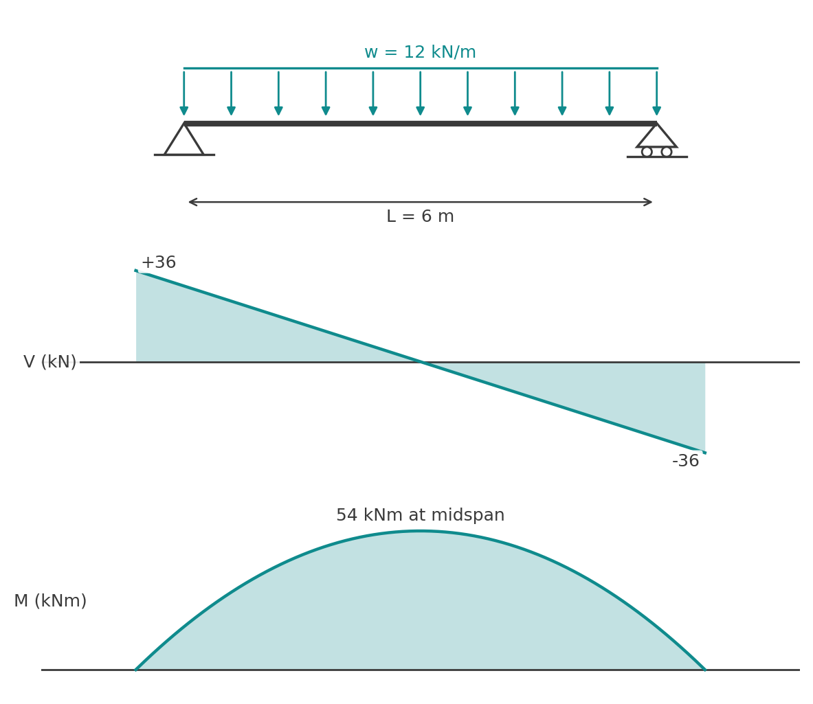
Check with the area rule: the area under the shear diagram from A to midspan is a triangle, \( \tfrac{1}{2} \times 3 \times 36 = 54 \) kNm. It matches.
Worked example 2: simply supported beam with an off-centre point load
Span \( L = 6 \) m, point load \( P = 40 \) kN at \( a = 2 \) m from A, so \( b = 4 \) m. Taking moments about B gives \( R_A \), and vertical equilibrium gives \( R_B \):
$$ R_A = \frac{Pb}{L} = \frac{40 \times 4}{6} = 26.67 \text{ kN}, \qquad R_B = \frac{Pa}{L} = \frac{40 \times 2}{6} = 13.33 \text{ kN} $$
To the left of the load, \( V = R_A = 26.67 \) kN and \( M = 26.67x \). To the right of it, \( V = 26.67 - 40 = -13.33 \) kN and \( M = 26.67x - 40(x - 2) \). The shear is constant in each segment and steps down by \( P \) at the load. The moment is linear in each segment and peaks under the load:
$$ M_{max} = \frac{Pab}{L} = \frac{40 \times 2 \times 4}{6} = 53.33 \text{ kNm} $$

The peak moment is under the load, not at midspan. Had the same load been central the peak would be \( PL/4 = 60 \) kNm, so moving a load towards a support reduces the moment it causes. The full set of cases is on the simply supported beam formulas page.
Worked example 3: cantilever with a tip load
Cantilevers are quickest to analyse from the free end, because then the reactions are never needed. For \( L = 3 \) m and \( P = 15 \) kN at the tip, cut at a distance \( x \) from the fixed end and look at the free side:
$$ V(x) = P = 15 \text{ kN}, \qquad M(x) = -P(L - x) $$
The shear is constant along the whole length. The moment is zero at the tip and grows linearly to its largest value at the support:
$$ M_{support} = -PL = -15 \times 3 = -45 \text{ kNm} $$

The negative sign means hogging: the top of the cantilever is in tension, which is why the main reinforcement in a concrete cantilever goes in the top. Under a UDL instead, \( V = w(L - x) \) and \( M = -w(L - x)^2/2 \), so the moment diagram becomes a parabola with its peak \( -wL^2/2 \) at the support. For \( w = 8 \) kN/m on a 4 m cantilever that is -64 kNm, with a support shear of 32 kN. More cases are on the cantilever beam formulas page.
Reading the diagrams
- The maximum shear is almost always at a support. For a UDL on a simple span it is \( wL/2 \).
- The maximum sagging moment is where the shear crosses zero. For a UDL on a simple span that is midspan, \( wL^2/8 \).
- Hogging moments appear at fixed ends, over the interior supports of continuous beams and at the root of cantilevers. They govern the top reinforcement or the top flange.
- A point of contraflexure is where \( M \) changes sign. It matters for lateral-torsional buckling checks and for deciding where bars can be curtailed.
- A moment diagram that does not return to zero at a pinned end means the reactions are wrong.
- Deflection follows from the moment diagram: integrate \( M/EI \) twice. The results for the common cases are on the beam deflection formulas page.
Standard cases
For a beam over several supports, the continuous beam calculator draws the same diagrams with the hogging moments over the supports.
- Simply supported, UDL \( w \): \( V_{max} = wL/2 \), \( M_{max} = wL^2/8 \) at midspan.
- Simply supported, central point load \( P \): \( V_{max} = P/2 \), \( M_{max} = PL/4 \).
- Simply supported, point load at \( a \) from one end: \( M_{max} = Pab/L \) under the load.
- Cantilever, tip load \( P \): \( V = P \) throughout, \( M_{max} = PL \) at the root.
- Cantilever, UDL \( w \): \( V_{max} = wL \), \( M_{max} = wL^2/2 \) at the root.
- Fixed both ends, UDL \( w \): \( M_{end} = wL^2/12 \) (hogging), \( M_{mid} = wL^2/24 \).
- Two equal continuous spans, UDL \( w \): \( M = wL^2/8 \) (hogging) over the middle support.
From diagrams to design
The peak values from the diagrams, computed from factored loads, are the design actions that get compared with the section capacity:
- Steel: AS 4100 Section 5 covers members in bending, with the section moment capacity in Cl 5.2 and the shear capacity of webs in Cl 5.11. The Eurocode equivalents are EN 1993-1-1 Cl 6.2.5 (bending) and Cl 6.2.6 (shear).
- Concrete: AS 3600 Section 8 gives beam strength in bending (Cl 8.1) and in shear (Cl 8.2). EN 1992-1-1 covers bending in Cl 6.1 and shear in Cl 6.2.
- Loads: the factored combinations, such as \( 1.2G + 1.5Q \), come from AS/NZS 1170.0 Cl 4.2.2 or EN 1990 Eq. 6.10.
In AS 4100 notation the requirement is \( M^* \le \phi M_s \) and \( V^* \le \phi V_v \); in the Eurocodes it is \( M_{Ed} \le M_{c,Rd} \) and \( V_{Ed} \le V_{c,Rd} \). The starred and Ed values are exactly the peaks read off the diagrams.
Run it in CalcTree
The beam analysis pack using Macaulay's theorem runs the three examples live and the continuous beam calculator extends them to multi-span beams. Every example above can be built as a live CalcTree page: enter the span, supports and loads, and the reactions, diagrams and peak actions update and can be checked line by line. The Beam Analysis Pack using Macaulay's Theorem covers the common simply supported and cantilever cases, and the template library has more.





