
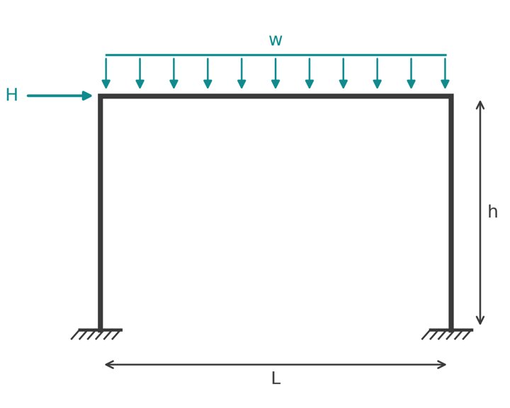
The main structural frame types, how support and joint conditions change the way a frame carries load, and a worked three-pinned portal frame example.
Structural frame types differ in one thing above all: how their joints and supports restrain rotation. A frame is a set of beams and columns connected so that they act together. Make the connections rigid and the frame resists sideways load by bending; make them pinned and it needs bracing to stand up. This guide sorts frames by their support and joint conditions, explains what each arrangement means for the analysis and the foundations, and works through the reactions and bending moment of a three-pinned portal frame by hand.
What a structural frame is
A frame carries gravity loads from floors and roofs down to the foundations and, in most buildings, also carries lateral loads from wind and earthquake. Its members are beams and columns (in a portal frame, rafters and columns), and the behaviour depends on how they are joined:
- A rigid or moment connection keeps the angle between the members fixed, so moment passes from beam to column.
- A pinned connection lets the members rotate relative to each other and transfers only shear and axial force.
This is what separates a frame from a truss, where every joint is pinned and every member carries axial force only, and from a single beam, which is one member on independent supports. In a rigid frame, a load on the beam bends the columns too, and a sideways push on the columns bends the beam.
Frame types by support and joint conditions
For a single-bay, single-storey frame the arrangement of supports and hinges decides how many unknown reactions there are. A plane structure has three equilibrium equations, so anything beyond three unknowns (less one for each internal hinge) is a redundant that needs a stiffness-based analysis.
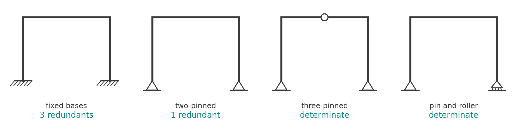
Rigid frame with fixed bases
Both columns fixed at the base and rigidly connected to the beam. Six reactions and three redundants. It is the stiffest arrangement: sway under lateral load is smallest, and the beam moment is shared with the columns. The price is base moments that the footings and holding-down bolts must resist, and sensitivity to foundation rotation, since a base that settles unevenly attracts moment it was not designed for. Concrete frames and heavy industrial steel frames are commonly modelled this way.
Two-pinned frame
Pinned bases, rigid beam-to-column connections. Four reactions, one redundant. The base moment is zero, so the footings only carry vertical load and horizontal thrust. This is the standard steel portal frame for warehouses and sheds: the knee joints do the work, the bases stay simple, and the single redundant is easy to handle in analysis software or with a published coefficient table.
Three-pinned frame
Pinned bases plus a hinge in the beam, usually at the ridge or midspan. Four reactions less one hinge release makes it statically determinate: reactions and internal forces come straight from equilibrium, as the worked example below shows. The frame is insensitive to support settlement and temperature, which is why it suits arches, timber and precast concrete frames erected in two halves. The cost is more deflection and larger eave moments than a two-pinned frame of the same size.
Pin and roller frame
One base pinned, the other on a roller. Three reactions, so it is determinate, and the roller lets the frame expand without thrust on the foundations. But the roller provides no horizontal restraint, so lateral stability depends entirely on the rigid joints and the pinned base. This arrangement models a frame on a sliding bearing, or a long structure with an expansion joint.
Frames with pinned beam-to-column joints
If the beams are pinned to the columns, the frame is a mechanism under lateral load unless something else stabilises it. This is "simple construction" in steel: cheap, bolted cleat connections, with stability provided by bracing or walls. The beams are designed as simply supported and the columns for axial load plus the small eccentricity moments from the beam reactions.
Braced and unbraced frames
The second way to classify frames is by how they resist lateral load.
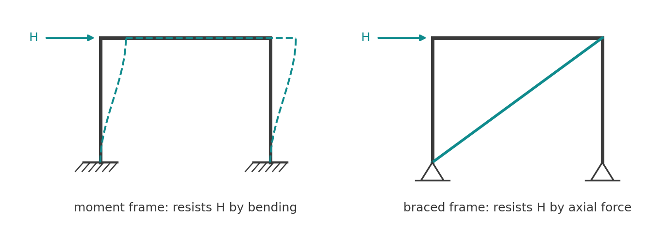
- A moment frame (unbraced, or sway frame) relies on rigid joints. Lateral load is resisted by bending in the beams and columns. It leaves the bays open, but the members work harder, sway is larger, and second-order effects from the vertical loads acting on the swayed shape have to be checked.
- A braced frame resists lateral load by axial force in diagonal bracing, or by shear walls or a core. The joints can be pinned, the members are lighter, and sway is small. The steel bracing systems guide covers the common bracing arrangements.
Both AS 4100 and EN 1993-1-1 draw this line explicitly. AS 4100 Cl 4.4 distinguishes braced from sway members and applies moment amplification factors to the first-order moments of a sway frame. EN 1993-1-1 Cl 5.2 uses the elastic critical load factor \( \alpha_{cr} \), and allows a first-order analysis only where \( \alpha_{cr} \ge 10 \). For concrete frames, AS 3600 Section 6 and EN 1992-1-1 Cl 5.8 cover second-order effects in the same way.
Where each type is used
- Single-storey industrial buildings: two-pinned steel portal frames, with the roof and wall bracing providing stability along the building.
- Multi-storey offices and apartments: concrete moment frames, or steel frames with simple connections braced by a core or by vertical bracing.
- Sports halls, timber and glulam structures: three-pinned frames, often as arches.
- Bridges, gantries and sign structures: rigid frames with fixed bases where the foundations can take the moment.
Worked example: a three-pinned portal frame
A portal frame has columns \( h = 5 \) m high and a flat beam spanning \( L = 10 \) m, with pinned bases A and B and a hinge C at midspan. The beam carries a UDL \( w = 10 \) kN/m. Find the reactions and draw the bending moment diagram.
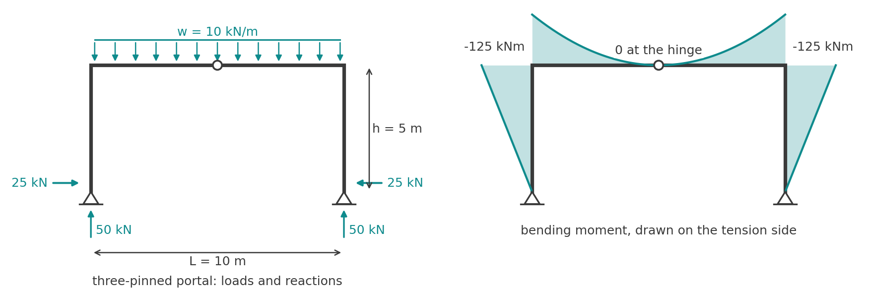
Step 1, vertical reactions. The load is symmetric, so each base takes half of it:
$$ V_A = V_B = \frac{wL}{2} = \frac{10 \times 10}{2} = 50 \text{ kN} $$
Step 2, horizontal reactions. The hinge at C carries no moment, so take moments about C for the right half of the frame on its own. The forces on that half are \( V_B \) upward at 5 m from C, \( H_B \) inward at the base 5 m below C, and the load on the right half of the beam, \( 10 \times 5 = 50 \) kN at 2.5 m from C:
$$ H_B \, h = V_B \frac{L}{2} - \frac{w}{2}\left(\frac{L}{2}\right)^2 \quad \Rightarrow \quad H_B = \frac{50 \times 5 - 5 \times 25}{5} = 25 \text{ kN} $$
Horizontal equilibrium of the whole frame gives \( H_A = H_B = 25 \) kN, both acting inward.
Step 3, column moments. Each column is a cantilever from the hinge at its base loaded by the horizontal reaction. The moment grows linearly from zero at the base to the eave:
$$ M_{eave} = H_A \, h = 25 \times 5 = 125 \text{ kNm} $$
It is hogging, with tension on the outside face of the column.
Step 4, beam moments. Cut the beam at a distance \( x \) from the left corner and take moments of everything to the left:
$$ M(x) = V_A x - H_A h - \frac{w x^2}{2} = 50x - 125 - 5x^2 $$
At \( x = 0 \) this gives -125 kNm, matching the column. At \( x = 2.5 \) m it is -31.25 kNm, and at the hinge \( x = 5 \) m it is \( 250 - 125 - 125 = 0 \), as it must be. The entire beam hogs, with the moment falling from 125 kNm at each corner to zero at the hinge.
Step 5, axial forces. The columns carry 50 kN compression. The beam carries the 25 kN horizontal thrust as compression, which is the force that would be absent in a simply supported beam.
Compare the same 10 m span as a simply supported beam: the midspan moment would be \( wL^2/8 = 125 \) kNm sagging. The three-pinned frame has moved that moment to the corners as hogging and put it into the columns as well, which is why the knee joints and the column bases get the attention in portal frame design.
The same approach works for lateral load. With a 20 kN horizontal force at the left eave and no gravity load, moments about A give \( V_B = 20 \times 5/10 = 10 \) kN upward and \( V_A = 10 \) kN downward; moments about C for the right half then give \( H_B = V_B \times 5/5 = 10 \) kN, so \( H_A = 10 \) kN, and each column carries a moment of \( 10 \times 5 = 50 \) kNm at the eave.
Analysing indeterminate frames
The 2D frame analysis with OpenSees solves a rigid, two-pinned or braced frame from a table of nodes, members, supports and loads and reports the reactions, member end forces and moment diagram.
Two-pinned and fixed-base frames need a compatibility condition for each redundant. For a single-bay portal the classical routes are the moment distribution method, slope-deflection, or published formulas that give the horizontal thrust as a function of the beam-to-column stiffness ratio. In practice a 2D stiffness analysis does it directly and also reports deflections, and the shear and moment diagrams it produces are read the same way as for a beam. The hand calculation above remains the check: for the fixed-base and two-pinned versions of the same frame, the gravity-case moments must still sum to the simply supported \( wL^2/8 \) across the beam, only shared differently between the corners and midspan.
Design codes
- Analysis: AS 4100 Section 4 and EN 1993-1-1 Cl 5 for steel; AS 3600 Section 6 and EN 1992-1-1 Cl 5 for concrete.
- Connections: AS 4100 Section 9 and EN 1993-1-8 for steel joints, including the classification of a joint as pinned, semi-rigid or rigid.
- Members: the columns are designed for combined axial force and bending, AS 4100 Section 8 or EN 1993-1-1 Cl 6.3.3, and the beams or rafters for bending with lateral restraint from the purlins.
Run it in CalcTree
The 2D frame analysis with OpenSees runs the indeterminate cases live. A frame analysis can be built as a live CalcTree page where the geometry, supports and loads are inputs and the reactions and moment diagrams are checkable outputs. The 2D frame analysis with OpenSees handles the indeterminate cases, and the three-pinned hand calculation above makes a good verification case for it.





