
Solve any plane frame online with finite element analysis. Enter nodes, members, supports and loads for reactions, forces, deflections, bending moment diagrams.

This template is not available yet. You can sign up and create it yourself!
Or let us know if you'd like to be notified when it’s ready:
No items found.
No items found.
About this 2D frame analysis calculator
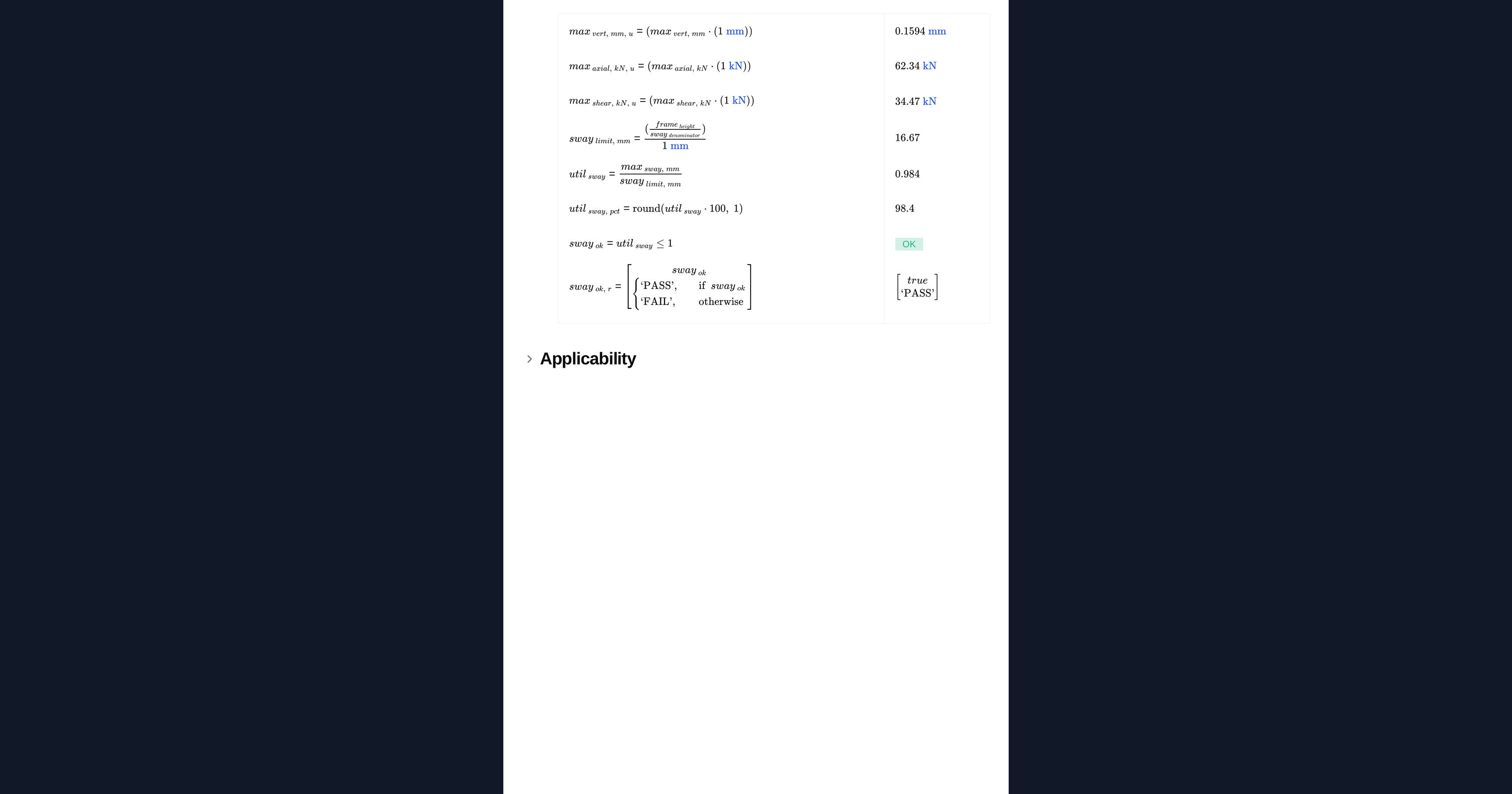
This is a general plane frame solver that runs a real finite element analysis (OpenSees) inside the page. You describe the structure as a table of nodes and members, add your supports and loads, and the calculation returns the reactions, member end forces and nodal displacements, together with the model, the deflected shape and the bending moment diagram drawn to scale.
Because the geometry is entered as a table rather than picked from a fixed catalogue, one page covers many structures. A portal frame, a multi-bay frame, a braced bent, a continuous beam over several supports and a pin-jointed truss are all the same analysis with different rows.
How it works
The frame is solved by the direct stiffness method. Each member is a two-node elastic beam-column with three degrees of freedom per node, so the model captures axial, shear and flexural behaviour together and the result is exact for a linear elastic frame rather than an estimate read off a standard case.
Setting up the input tables
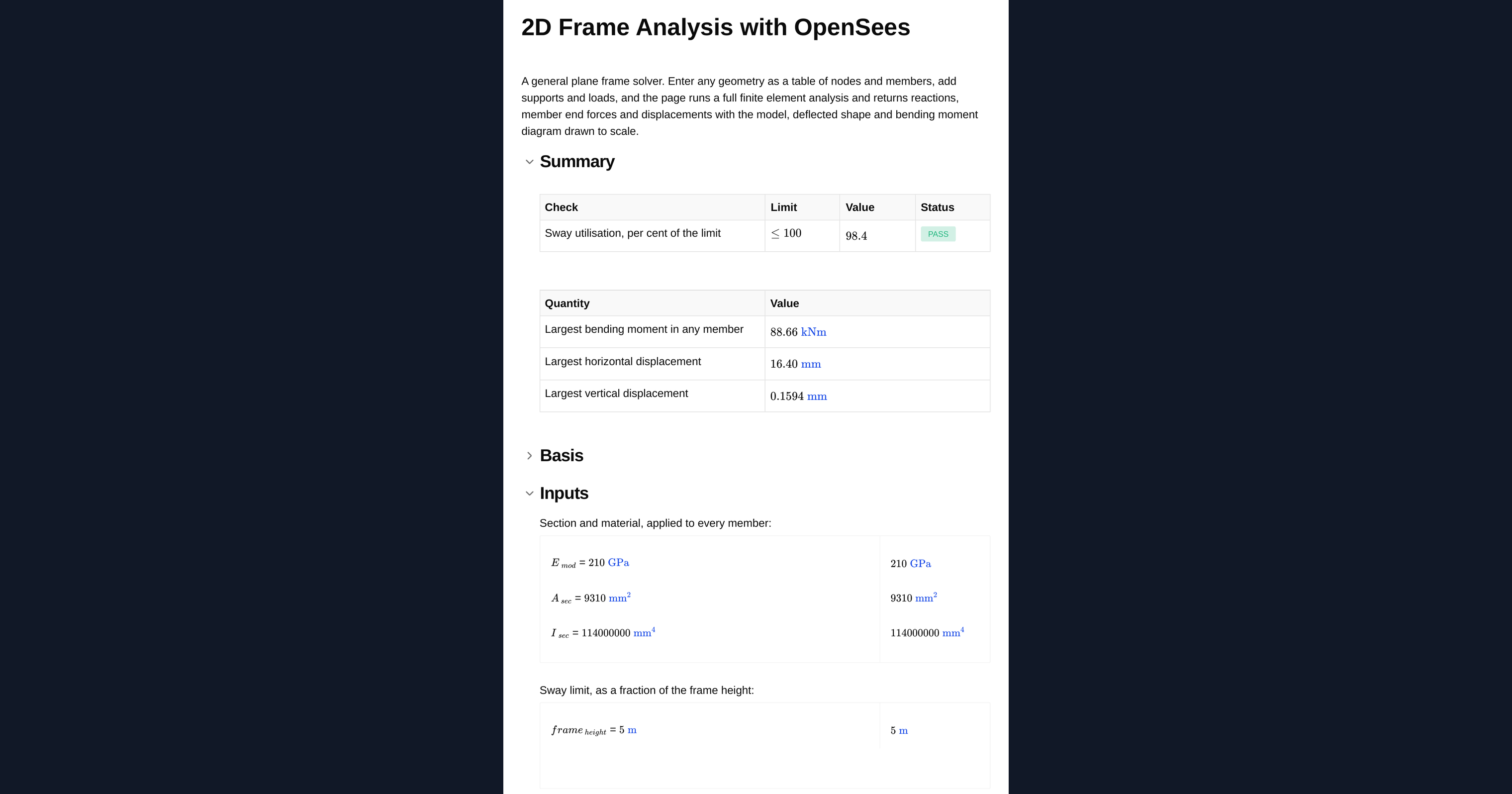
- Nodes: tag, then x and y in metres.
- Members: tag, then the start and end node tags. The member runs from start to end, which sets the sign of its local end forces.
- Supports: node tag, then 1 for restrained or 0 for free in x, y and rotation. A pin is
1 1 0, a fixed base is1 1 1, and a roller on a horizontal surface is0 1 0. - Point loads: node tag, then the horizontal force, vertical force and moment. Forces are in kN, moments in kNm, positive to the right and upwards.
- Member loads: member tag, then a uniformly distributed load in kN/m acting perpendicular to the member, negative downwards on a horizontal member.
Every member takes the same section properties, which you enter below the tables.
Assumptions and limits
The analysis is first order and linear elastic. It does not include second-order effects, so where the vertical load is a significant fraction of the frame's elastic critical load the sway moments reported here understate the real ones and a second-order analysis is needed. Material is elastic throughout with no yielding, and connections are treated as fully rigid unless you model a release by splitting the member.
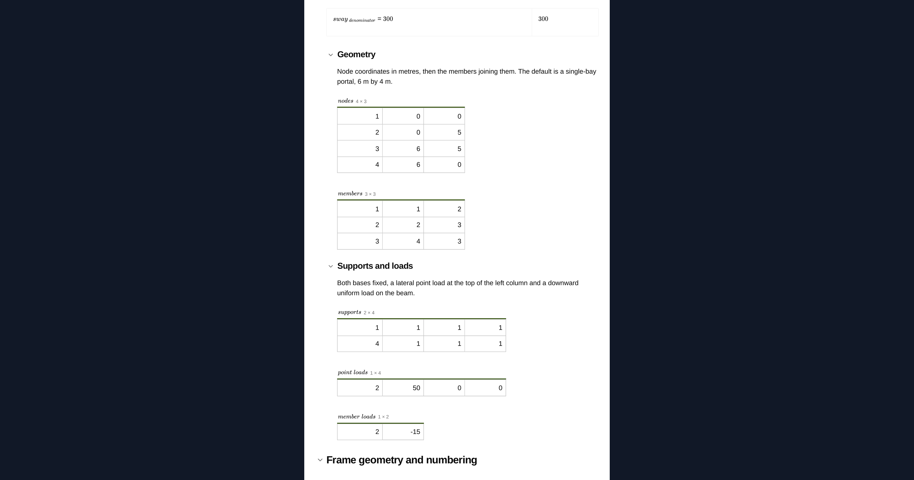
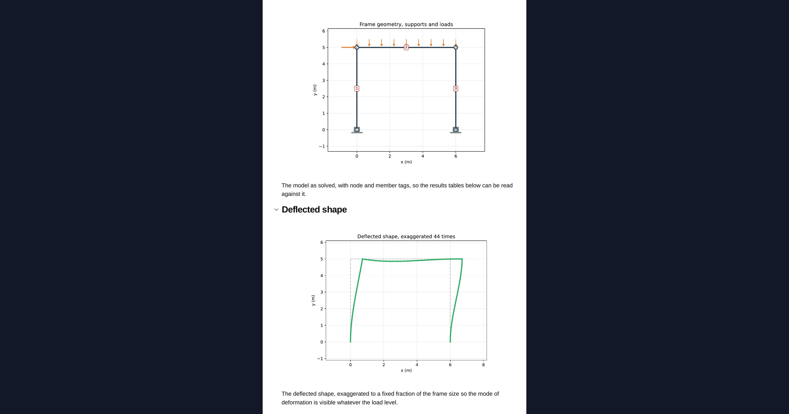
Every member carries the same section. For a frame with different sections, run the governing members separately or extend the member table with per-member properties. Member loads are uniform over the full member length and act perpendicular to it, so a partial or inclined load must be resolved into equivalent nodal loads. Self weight is not applied automatically; add it as a member load if it matters. The deflected shape is exaggerated for legibility and is not to scale against the geometry.
Every input, formula and result is visible and editable, so you can adapt the model to your own frame and keep it as an auditable record of the analysis.
Engineering templates
Common calculators
Design guides




Frequently asked questions
What structures can this calculator analyse?
Any plane frame you can describe as nodes and members. Portal and multi-bay frames, braced bents, continuous beams over several supports and pin-jointed trusses are all handled by changing the rows in the input tables rather than switching to a different calculation.
What analysis method does it use?
The direct stiffness method with two-node elastic beam-column members and three degrees of freedom per node. It captures axial, shear and flexural behaviour together, so the solution is exact for a linear elastic frame.
Does it include second-order (P-delta) effects?
No. This is a first-order, linear elastic analysis. Where the vertical load is a significant fraction of the frame's elastic critical load, the sway moments here understate the real ones and you should run a second-order analysis.
Can members have different sections?
Every member uses the same section properties as entered. For a frame with mixed sections, run the governing members separately or extend the member table with per-member properties.
How do I model a pin, a fixed base or a roller?
In the supports table, use 1 for restrained and 0 for free in x, y and rotation. A pin is 1 1 0, a fixed base is 1 1 1 and a roller on a horizontal surface is 0 1 0.
Is self weight included?
No. Self weight is not applied automatically. Add it as a uniformly distributed member load if it is relevant to your case.
How do I apply a partial or inclined load?
Member loads are uniform over the full member length and act perpendicular to the member. Resolve a partial or inclined load into equivalent nodal point loads and enter those instead.
What results does it return?
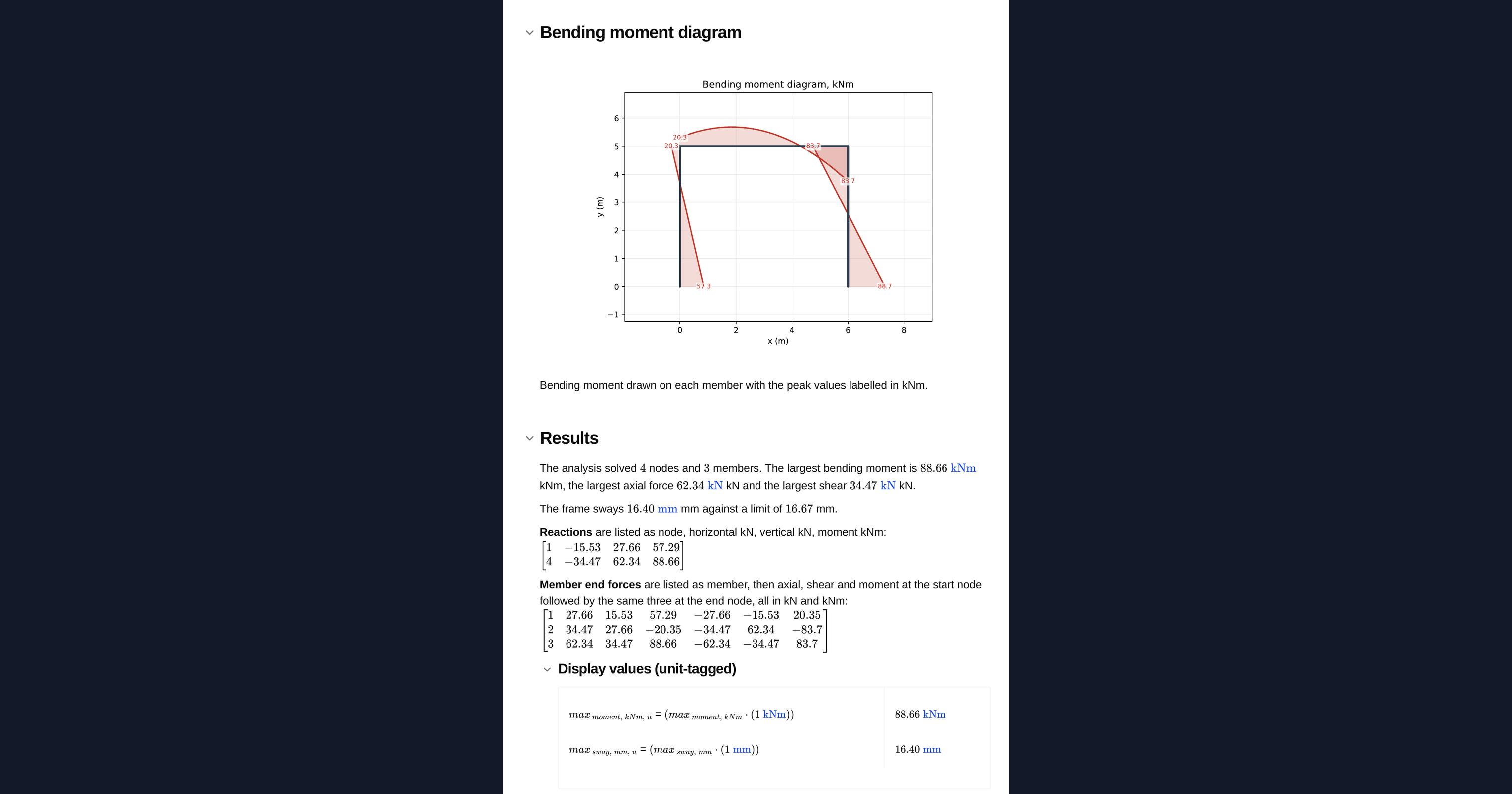
Reactions, member end forces and nodal displacements, plus the model, the deflected shape and the bending moment diagram. The deflected shape is exaggerated for legibility and is not to scale against the geometry.
Learn about the benefits of using CalcTree on engineering projects!