
Solve any 2D pin-jointed truss. Enter nodes, members, supports and loads to get member forces, reactions and joint deflections from a real OpenSees analysis.

This template is not available yet. You can sign up and create it yourself!
Or let us know if you'd like to be notified when it’s ready:
No items found.
No items found.
About this online 2D truss analysis calculator
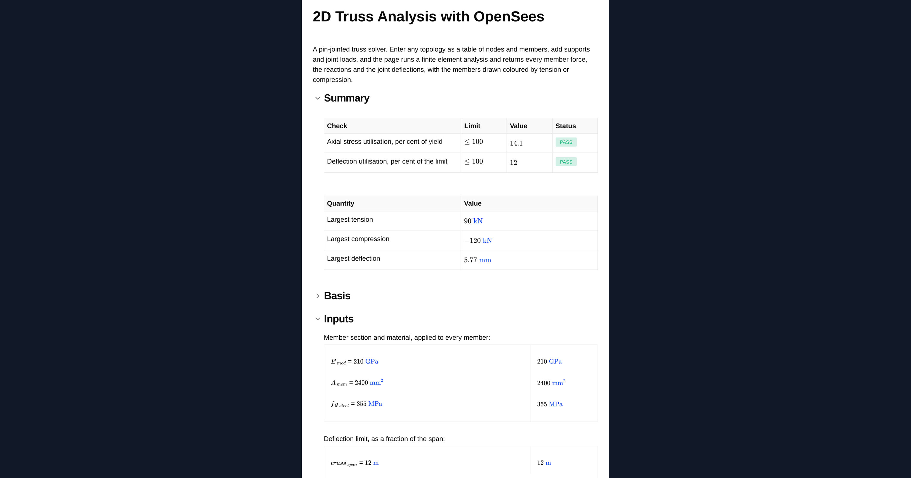
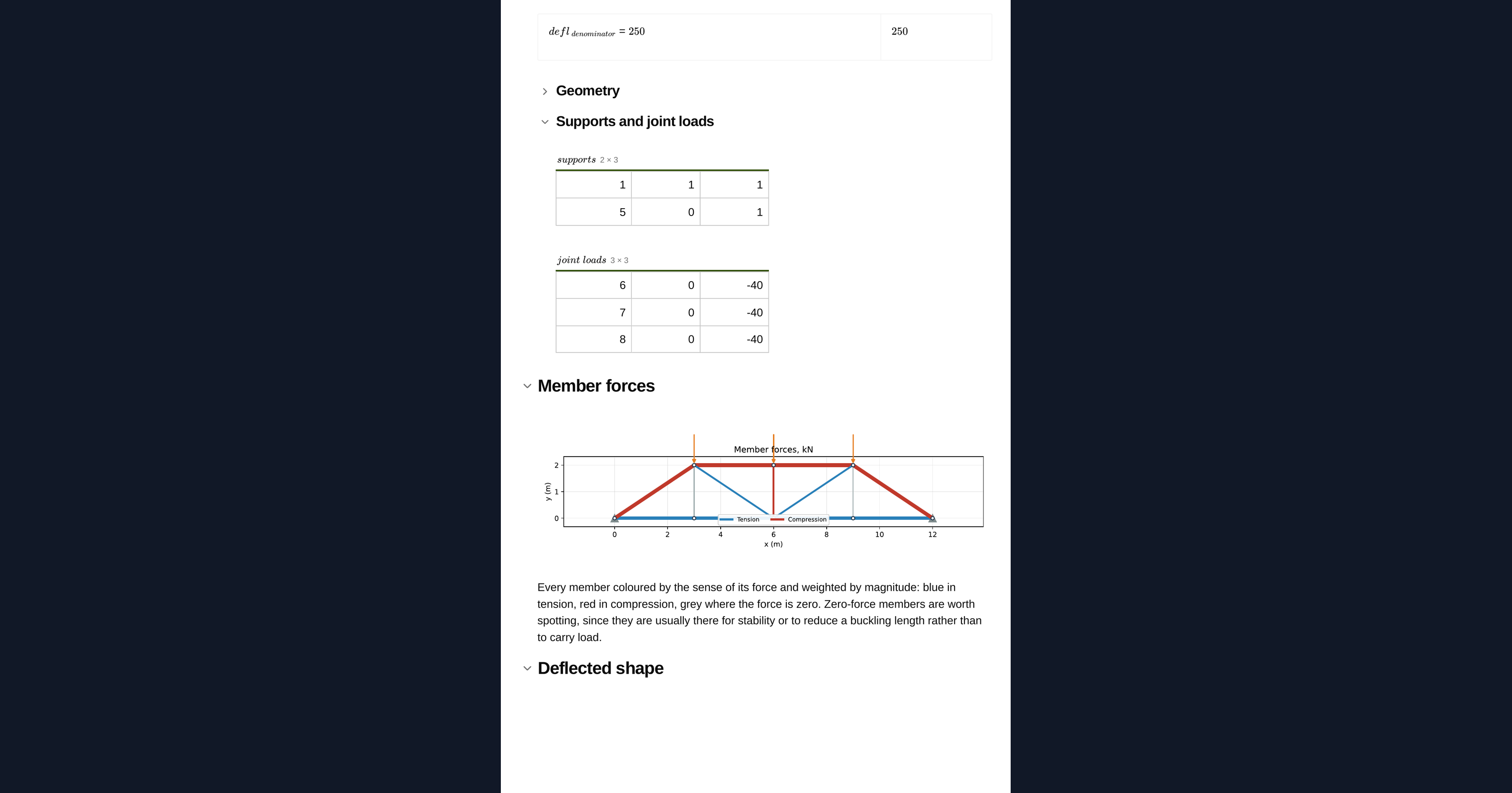
This calculator solves any planar pin-jointed truss you can describe. You enter the topology as two tables, a list of nodes and a list of members, add your supports and joint loads, and the page runs a finite element analysis and returns every member force, the support reactions and the joint deflections. The members are drawn coloured by whether they are in tension or compression, so you can read the load path at a glance.
How the analysis works
Every member is treated as a two-force pin-jointed bar carrying axial load only, so each node has two degrees of freedom and the solution follows from the direct stiffness method. The result is exact for a pin-jointed assembly. Unlike a method-of-joints hand calculation, it does not care whether the truss is statically determinate, so a redundant member is handled by the same solve.
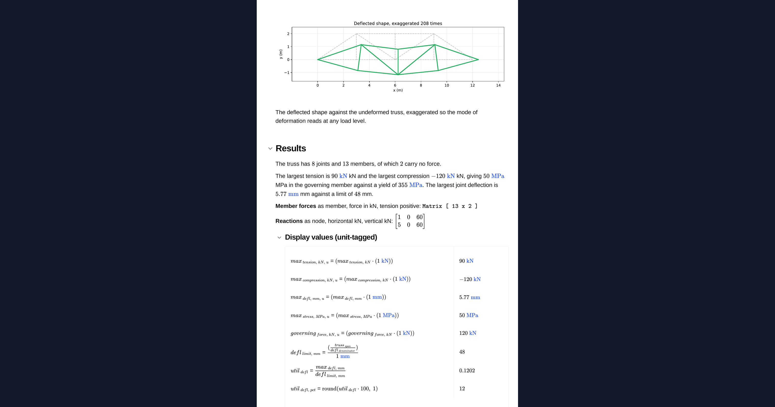
The engine behind the page is OpenSees, a real finite element analysis running in the page itself. Because the geometry comes from a table rather than a fixed standard case, you can analyse arbitrary layouts, and you get diagrams and contour plots alongside the numbers.
How to set up the input tables
- Nodes: tag, then the x and y coordinates in metres.
- Members: tag, then the two node tags the member connects.
- Supports: node tag, then 1 for restrained or 0 for free in x and y. A pin is
1 1, and a roller on a horizontal surface is0 1. - Joint loads: node tag, then the horizontal and vertical force in kN, positive to the right and upwards.
Tension is positive throughout. The default worked example is a 12 m Pratt truss, 2 m deep, with 40 kN applied at each top panel point, so you can see the format before you enter your own frame.
Assumptions and limits you need to know
A pin-jointed model carries no moment. A member loaded between its nodes, or a joint stiff enough to attract moment, sits outside this analysis and needs a frame model instead.
The stress check is against yield only. Every compression member still needs its own buckling check, on its own effective length and about the governing axis. For a slender chord or web member, buckling almost always governs rather than yield, and this page does not do that check.
Joints are taken as frictionless pins and loads are applied only at joints. A real bolted or welded joint carries some moment, which adds secondary stresses this analysis does not capture, and a purlin landing between panel points puts bending into the chord that must be assessed separately.
Every member takes the same area. For a truss with heavier chords than webs the member forces are unaffected, because they follow from statics wherever the truss is determinate, but the deflections are not. Re-run with the governing area or model the members individually. Self weight is not applied automatically.
This calculator is intended to support engineering judgement, not replace it. Always check the results against your own analysis and the relevant design code.
Engineering templates
Common calculators
Design guides



Frequently asked questions
What type of truss can I analyse?
Any planar pin-jointed truss. You describe the geometry as a table of nodes and members, so you are not limited to a fixed standard case. Pratt, Warren, Howe, King and Queen posts, and irregular or custom layouts all work.
Does the truss have to be statically determinate?
No. The solution uses the direct stiffness method, so a redundant, indeterminate truss is handled by the same solve. This is one of the advantages over a method-of-joints hand calculation.
What results does the calculator return?
The axial force in every member, the reactions at every support and the deflection at every joint. The members are drawn coloured by tension or compression, and the page produces diagrams and contour plots alongside the numbers.
What is the sign convention?
Tension is positive throughout. Joint loads are positive to the right and upwards, and support restraints use 1 for restrained and 0 for free in each direction.
Does the calculator check for buckling?
No. The stress check is against yield only. Every compression member still needs its own buckling check on its own effective length and about the governing axis. For slender members buckling almost always governs, so this must be done separately.
Can I model a member with load applied along its length?
Not in this analysis. A pin-jointed model carries no moment, so a member loaded between its nodes puts bending into the chord that this page does not capture. Use a frame model for that case, and assess a purlin landing between panel points separately.
Do member areas affect the results?
Every member is given the same area. Where the truss is determinate the member forces follow from statics and are unaffected by area, but the deflections do depend on it. Re-run with the governing area or model members individually if deflection matters. Self weight is not applied automatically.
Learn about the benefits of using CalcTree on engineering projects!