
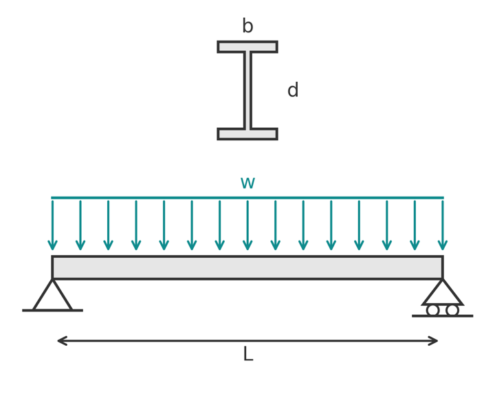
How to design a steel beam for bending, shear, lateral torsional buckling and deflection to AS 4100 and EN 1993-1-1, with a worked example on a 360UB50.7.
Steel beam design is a fixed sequence of checks: find the actions, classify the section, then verify bending, shear, lateral torsional buckling and deflection. Every steel code runs the same sequence. What changes between AS 4100 and EN 1993-1-1 (Eurocode 3) is the notation, the safety factors and a few of the formulas, so this guide walks the two side by side and finishes with one worked example to AS 4100.
If you need the beam formulas themselves, see simply supported beam moment and shear formulas and beam deflection formulas. This page is about the capacity side.
The design sequence
- Fix the static system: span, supports and lateral restraint points.
- Collect the characteristic loads and combine them for the ultimate (ULS) and serviceability (SLS) limit states.
- Choose a trial section and classify it (compact, non-compact or slender in AS 4100; Class 1 to 4 in Eurocode 3).
- Find the design bending moment and shear force.
- Check section moment capacity, shear capacity and the interaction between them.
- Check lateral torsional buckling (LTB) for each segment between restraints.
- Check deflection under service loads.
Typical cases are floor beams in steel framed buildings, roof beams and purlins, crane runway beams and transfer beams. A floor beam with a concrete slab on top is laterally restrained along its length, so LTB rarely governs; an exposed roof beam or a transfer beam between widely spaced restraints is where LTB decides the section.
Static system and loads
Most steel beams are designed as simply supported, even where the connections carry some moment, because a simple web cleat or fin plate connection cannot be relied on for continuity. Treating the beam as pinned is conservative for the span moment and gives a clean load path.
Load transfer
Loads arrive as area loads on the slab or roof (kPa) and become a line load on the beam by multiplying by the tributary width. A beam at 3 m centres carrying a 5 kPa dead load sees 15 kN/m from that source. Add the self-weight of the beam. Our guide to structural load calculations covers the build-up of dead, superimposed dead and live loads.
Load combinations
- AS/NZS 1170.0: the governing gravity combination is \(1.2G + 1.5Q\) (with \(1.35G\) for permanent action alone).
- EN 1990: \(1.35G_k + 1.5Q_k\).
Serviceability uses unfactored loads: \(G + \psi_s Q\) or \(G + \psi_l Q\) in AS/NZS 1170.0, and the characteristic, frequent or quasi-permanent combinations in EN 1990.
Section properties and classification
You need the second moment of area \(I\), the elastic section modulus \(Z\) (\(W_{el}\) in Eurocode), the plastic section modulus \(S\) (\(W_{pl}\)), and for LTB the minor axis \(I_y\), the torsion constant \(J\) and the warping constant \(I_w\). Section tables give all of these; our moment of inertia guide shows where they come from.
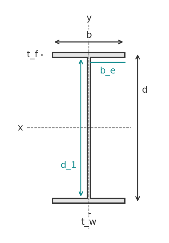
Classification asks whether the flange outstand and the web can reach yield, and then plastic rotation, before they buckle locally. Both codes compare a plate slenderness against limits.
- AS 4100: plate slenderness \(\lambda_e = (b/t)\sqrt{f_y/250}\). A section is compact if every element is within \(\lambda_{ep}\), non-compact if within \(\lambda_{ey}\), slender beyond that. For a hot-rolled flange outstand under uniform compression \(\lambda_{ep} = 9\) and \(\lambda_{ey} = 16\); for a web in bending \(\lambda_{ep} = 82\) and \(\lambda_{ey} = 115\).
- EN 1993-1-1 Clause 5.5.2 and Table 5.2: \(\varepsilon = \sqrt{235/f_y}\). A flange outstand is Class 1 at \(c/t \le 9\varepsilon\), Class 2 at \(10\varepsilon\), Class 3 at \(14\varepsilon\). A web in bending is Class 1 at \(c/t \le 72\varepsilon\), Class 2 at \(83\varepsilon\), Class 3 at \(124\varepsilon\).
Compact (Class 1 or 2) sections use the plastic modulus. Non-compact (Class 3) sections use the elastic modulus. Slender (Class 4) sections use a reduced effective section. Nearly all hot-rolled universal beams are compact in bending.
Internal forces
For a simply supported beam under a uniformly distributed design load \(w^*\) over span \(L\):
$$ M^* = \frac{w^* L^2}{8}, \qquad V^* = \frac{w^* L}{2} $$
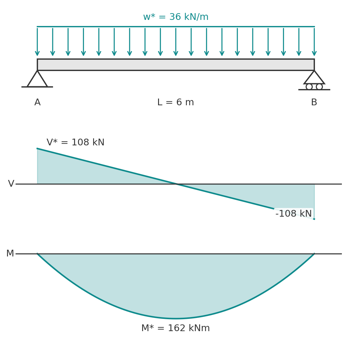
Eurocode writes the same quantities as \(M_{Ed}\) and \(V_{Ed}\). Our shear force and bending moment diagram guide covers other load cases.
Bending: section moment capacity
- AS 4100: \(M^* \le \phi M_s\) with \(\phi = 0.9\) and \(M_s = f_y Z_e\). For a compact section \(Z_e = \min(S,\ 1.5Z)\).
- EN 1993-1-1 Equation 6.13: \(M_{Ed} \le M_{c,Rd}\) with \(M_{c,Rd} = W_{pl} f_y / \gamma_{M0}\) for Class 1 and 2, \(W_{el,min} f_y / \gamma_{M0}\) for Class 3. The recommended \(\gamma_{M0} = 1.0\); check your National Annex.
The practical difference: AS 4100 puts the safety margin in \(\phi = 0.9\) on the resistance side, Eurocode puts almost all of it on the load side with \(\gamma_{M0} = 1.0\).
Shear
- AS 4100: \(V^* \le \phi V_v\). For a web with \(d_p/t_w \le 82/\sqrt{f_y/250}\) the web yields before it buckles and \(V_v = V_w = 0.6 f_y A_w\), with \(A_w = d\,t_w\) for a hot-rolled section. Beyond that limit the standard reduces the capacity for shear buckling.
- EN 1993-1-1 Equation 6.18: \(V_{Ed} \le V_{pl,Rd} = A_v f_y / (\sqrt{3}\,\gamma_{M0})\), with the shear area \(A_v\) for a rolled I-section given in the standard. If \(h_w/t_w > 72\varepsilon/\eta\) the web must be checked for shear buckling to EN 1993-1-5.
Bending and shear together
Both codes let you ignore the interaction when shear is low. AS 4100 needs no reduction while \(V^* \le 0.6\,\phi V_v\); above that the moment capacity drops linearly as the shear rises to \(\phi V_v\). EN 1993-1-1 needs no reduction while \(V_{Ed} \le 0.5 V_{pl,Rd}\); above that the yield stress of the shear area is reduced by \((1 - \rho)\) with \(\rho = (2V_{Ed}/V_{pl,Rd} - 1)^2\). On a simply supported beam the peak moment and peak shear occur at different points, so interaction seldom governs.
Lateral torsional buckling
A beam bent about its strong axis can fail by the compression flange moving sideways and the section twisting, well below the section moment capacity. The check runs per segment between points of effective lateral restraint, and the capacity depends on the segment length, the moment shape within it, and the minor axis, torsional and warping stiffness of the section.
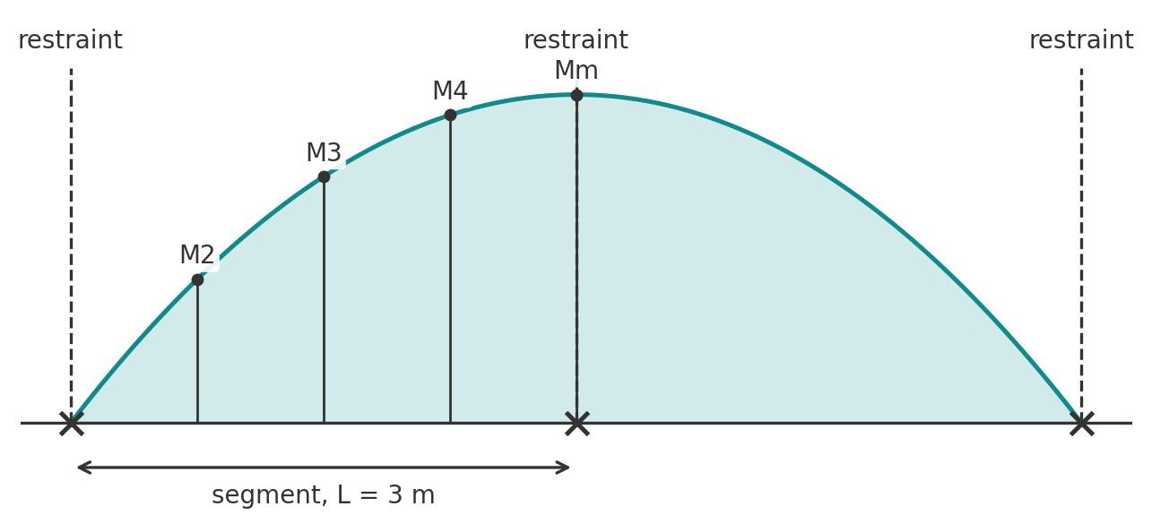
- AS 4100: \(M_b = \alpha_m \alpha_s M_s \le M_s\), checked as \(M^* \le \phi M_b\). The reference buckling moment is $$ M_o = \sqrt{\left(\frac{\pi^2 E I_y}{l_e^2}\right)\left(G J + \frac{\pi^2 E I_w}{l_e^2}\right)} $$ and the slenderness reduction factor is \(\alpha_s = 0.6\left[\sqrt{(M_s/M_o)^2 + 3} - M_s/M_o\right]\). The moment modification factor \(\alpha_m\) comes from the standard's table or from \(\alpha_m = 1.7 M^*_m / \sqrt{(M^*_2)^2 + (M^*_3)^2 + (M^*_4)^2} \le 2.5\), using the moments at the quarter points of the segment. The effective length \(l_e = k_t k_l k_r L\) accounts for twist restraint, load height and lateral rotation restraint at the segment ends.
- EN 1993-1-1 Equations 6.55 to 6.57: \(M_{Ed} \le M_{b,Rd} = \chi_{LT} W_y f_y / \gamma_{M1}\). Compute the elastic critical moment \(M_{cr}\) (the same expression as \(M_o\), with a moment shape factor), then \(\bar\lambda_{LT} = \sqrt{W_y f_y / M_{cr}}\), \(\Phi_{LT} = 0.5[1 + \alpha_{LT}(\bar\lambda_{LT} - 0.2) + \bar\lambda_{LT}^2]\) and \(\chi_{LT} = 1/(\Phi_{LT} + \sqrt{\Phi_{LT}^2 - \bar\lambda_{LT}^2}) \le 1\). The imperfection factor \(\alpha_{LT}\) comes from Table 6.3 and the buckling curve from Table 6.4; Equation 6.57 gives a less conservative version for rolled sections, with a plateau length of 0.4 and a factor of 0.75 on the squared slenderness.
If the compression flange is continuously restrained, for example by a composite slab or by decking screwed to the top flange of a roof beam, set \(M_b = M_s\) and move on.
Deflection
For a uniformly loaded simply supported beam the midspan deflection is \(\delta = 5 w L^4 / (384 E I)\), with \(E = 200\) GPa in AS 4100 and \(210\) GPa in Eurocode 3. Neither code hard-codes a limit. AS 4100 and AS/NZS 1170.0 give suggested limits; EN 1993-1-1 Clause 7.2.1 points to the National Annex. Common office-floor values are span/360 under live load and span/250 under total load, tightened where brittle finishes sit on the beam.
Worked example: 360UB50.7 to AS 4100
A simply supported floor beam spans 6.0 m. It carries \(G = 15\) kN/m including self-weight and \(Q = 12\) kN/m. Secondary beams restrain the compression flange at the ends and at midspan. Trial section: 360UB50.7, Grade 300. The flange is 11.5 mm thick so \(f_y = 300\) MPa, and we use that for the whole section (the thinner web is 320 MPa, so this is slightly conservative).
Section properties: \(d = 356\) mm, \(b_f = 171\) mm, \(t_f = 11.5\) mm, \(t_w = 7.3\) mm, \(I_x = 142 \times 10^6\) mm\(^4\), \(Z_x = 798 \times 10^3\) mm\(^3\), \(S_x = 897 \times 10^3\) mm\(^3\), \(I_y = 9.60 \times 10^6\) mm\(^4\), \(J = 241 \times 10^3\) mm\(^4\), \(I_w = 284 \times 10^9\) mm\(^6\).
1. Actions
$$ w^* = 1.2(15) + 1.5(12) = 36\ \text{kN/m}, \quad M^* = \frac{36 \times 6^2}{8} = 162\ \text{kNm}, \quad V^* = \frac{36 \times 6}{2} = 108\ \text{kN} $$
2. Classification
Flange outstand: \(\lambda_e = \frac{(171 - 7.3)/2}{11.5}\sqrt{300/250} = 7.8 \le 9\). Web: \(\lambda_e = \frac{356 - 2(11.5)}{7.3}\sqrt{300/250} = 50.0 \le 82\). Compact, so \(Z_e = \min(897, 1.5 \times 798) \times 10^3 = 897 \times 10^3\) mm\(^3\).
3. Section moment capacity
$$ M_s = 300 \times 897 \times 10^3 = 269.1\ \text{kNm}, \qquad \phi M_s = 242.2\ \text{kNm} \ge 162\ \text{kNm} $$
4. Shear
\(d_p/t_w = 333/7.3 = 45.6 \le 82/\sqrt{1.2} = 74.9\), so the web yields: \(V_w = 0.6 \times 300 \times 356 \times 7.3 = 467.8\) kN and \(\phi V_v = 421.0\) kN \(\ge 108\) kN. Since \(V^* \le 0.6\phi V_v = 252.6\) kN there is no reduction to the moment capacity.
5. Lateral torsional buckling
Segment length 3.0 m between restraints. Take \(k_t = k_l = k_r = 1.0\), so \(l_e = 3000\) mm, with \(E = 200\) GPa and \(G = 80\) GPa:
$$ M_o = \sqrt{\frac{\pi^2 (200\times10^3)(9.60\times10^6)}{3000^2}\left[80\times10^3 (241\times10^3) + \frac{\pi^2 (200\times10^3)(284\times10^9)}{3000^2}\right]} = 414.4\ \text{kNm} $$
$$ \alpha_s = 0.6\left[\sqrt{(269.1/414.4)^2 + 3} - 269.1/414.4\right] = 0.720 $$
In the segment from the support to midspan the moment rises from 0 to 162 kNm. Quarter-point moments at 0.75, 1.5 and 2.25 m from the support are 70.9, 121.5 and 151.9 kNm, so
$$ \alpha_m = \frac{1.7 \times 162}{\sqrt{70.9^2 + 121.5^2 + 151.9^2}} = 1.33 $$
$$ M_b = 1.33 \times 0.720 \times 269.1 = 257.9\ \text{kNm} \le M_s, \qquad \phi M_b = 232.1\ \text{kNm} \ge 162\ \text{kNm} $$
Utilisation 0.70. With a slab restraining the top flange continuously this check would not be needed at all.
6. Deflection
$$ \delta_Q = \frac{5 \times 12 \times 6000^4}{384 \times 200\times10^3 \times 142\times10^6} = 7.1\ \text{mm} \le \frac{6000}{360} = 16.7\ \text{mm} $$
Under \(G + Q\) the deflection is 16.0 mm against span/250 = 24 mm. The 360UB50.7 passes every check, with LTB the closest at 70 percent.
In Eurocode 3 the same beam would be checked with \(w_{Ed} = 1.35 \times 15 + 1.5 \times 12 = 42.3\) kN/m, so \(M_{Ed} = 190\) kNm, against \(M_{c,Rd} = W_{pl} f_y / 1.0\). The load factors are higher and the resistance factor is 1.0, and for most gravity cases the two codes land within a few percent of each other.
Run it in CalcTree
Every step above is a formula on a section property, so the whole beam check can be built as a live, checkable CalcTree page where the section, span and loads are inputs and each check reports its utilisation. Start from the Steel Member Design to AS 4100 template, or the Steel Section Designer to Eurocode 3 for the EN 1993-1-1 version. For columns, see steel column design.





