
How to design a steel column for compression and flexural buckling to AS 4100 and EN 1993-1-1: effective lengths, buckling curves and a worked HEB 200 example.
Steel column design comes down to two questions: can the cross-section carry the axial load without yielding or buckling locally, and can the member carry it without buckling as a whole. The second question is the one that normally governs, and it depends on the effective length, the radius of gyration and the buckling curve the code assigns to the section. This guide runs the check sequence to AS 4100 and EN 1993-1-1 (Eurocode 3) side by side, then works one example to Eurocode 3.
It covers concentric compression only. Columns carrying moment as well, which is most columns in a rigid frame, add a combined-actions check (in both AS 4100 and EN 1993-1-1) on top of what follows.
The design sequence
- Fix the static system: height, end restraints about each axis, and any intermediate restraint.
- Collect the characteristic loads and combine them for the ultimate limit state.
- Choose a trial section and classify it for pure compression.
- Check the section capacity (squash load, reduced for slender elements).
- Find the effective length and slenderness about each axis.
- Check the member buckling capacity about each axis. The lower one governs.
Typical steel columns are the posts of a braced multi-storey frame, portal frame columns, props under transfer beams and the chords of a truss, which are columns between the panel points.
Static system and effective length
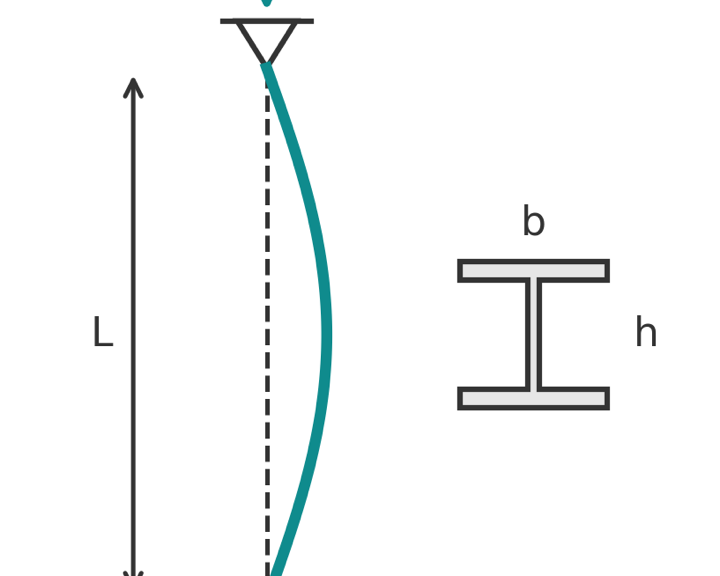
A column in a braced frame is normally idealised as pinned at both ends. The buckling length is then the storey height between restraints. Where the ends are stiffer, or where the frame sways, the effective length changes, and this is the input that most often goes wrong.

The theoretical values are 1.0 for pinned-pinned, 0.5 for fixed-fixed, 0.7 for fixed-pinned and 2.0 for a fixed-free cantilever. AS 4100 gives design values that allow for real, imperfect fixity: 1.0, 0.7, 0.85 and 2.2, plus 1.2 for a column fixed at the base and free to sway at the top. EN 1993-1-1 leaves the buckling length to the designer; the usual practice is the theoretical values for braced frames and a frame analysis, or a National Annex method, for sway frames. The effective length can differ about the two axes: a column restrained at mid-height by girts about its weak axis but not its strong axis has two different buckling lengths.
Loads and load combinations
Column loads accumulate storey by storey from the beams framing in. Floor loads come down as reactions of the beams; our structural load calculation guide covers the build-up. Live load reduction for columns supporting several floors is allowed by both AS/NZS 1170.1 and EN 1991-1-1, and it matters: a column under six office floors sees a much lower reduced live load than six times the single-floor value.
- AS/NZS 1170.0: \(N^* = 1.2G + 1.5Q\) for the gravity case.
- EN 1990: \(N_{Ed} = 1.35G_k + 1.5Q_k\).
Section properties and classification
For a column you need the gross area \(A\), the second moments of area about both axes and the radii of gyration \(r = \sqrt{I/A}\) (\(i\) in Eurocode notation). Universal columns and HE sections are proportioned so that the weak-axis radius of gyration is as large as practical, which is why they look squarer than beams.
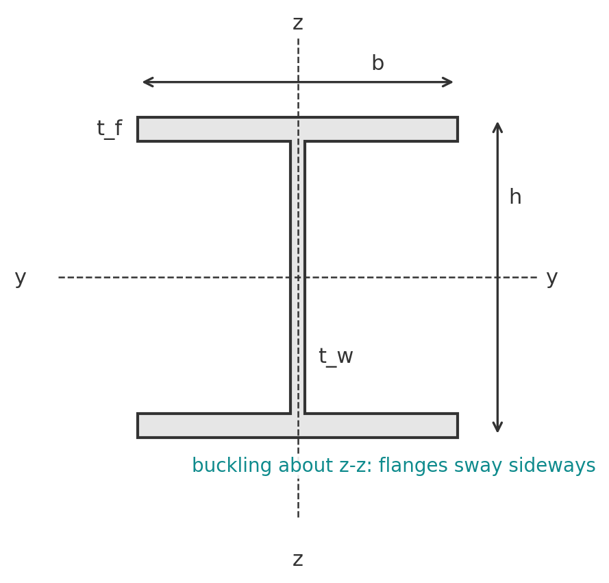
In pure compression every plate element is in uniform compression, so the limits are tighter than for bending.
- AS 4100: the form factor \(k_f = A_e / A_g\), where the effective area \(A_e\) is reduced for any element whose slenderness \(\lambda_e = (b/t)\sqrt{f_y/250}\) exceeds the yield limit \(\lambda_{ey}\). For most hot-rolled UC sections \(k_f = 1.0\).
- EN 1993-1-1 Clause 5.5.2 and Table 5.2: a flange outstand is Class 3 or better at \(c/t \le 14\varepsilon\); an internal web in compression at \(c/t \le 42\varepsilon\), with \(\varepsilon = \sqrt{235/f_y}\). Class 1 to 3 sections use the gross area. Class 4 sections use an effective area to EN 1993-1-5.
Section capacity
- AS 4100: \(N^* \le \phi N_s\), \(N_s = k_f A_n f_y\), \(\phi = 0.9\).
- EN 1993-1-1 Equation 6.10: \(N_{Ed} \le N_{c,Rd} = A f_y / \gamma_{M0}\) (or \(A_{eff} f_y/\gamma_{M0}\) for Class 4), with the recommended \(\gamma_{M0} = 1.0\).
This is the squash load. A column only reaches it when it is very stocky, so the section capacity is an upper bound rather than the usual governing check.
Member buckling capacity
Both codes start from the Euler load \(N_{cr} = \pi^2 E I / L_{cr}^2\), then reduce it with a curve calibrated to tests on real columns with residual stresses and initial out-of-straightness. The curve depends on the section type, the axis of buckling and the plate thickness.
AS 4100
\(N^* \le \phi N_c\) with \(N_c = \alpha_c N_s \le N_s\). The modified slenderness is
$$ \lambda_n = \frac{l_e}{r}\sqrt{k_f}\sqrt{\frac{f_y}{250}} $$
The member section constant \(\alpha_b\) (tabulated in the standard) takes one of five values from -1.0 to 1.0, and the slenderness reduction factor \(\alpha_c\) is then read from the standard's table or computed from its closed-form expressions:
$$ \alpha_a = \frac{2100(\lambda_n - 13.5)}{\lambda_n^2 - 15.3\lambda_n + 2050}, \quad \lambda = \lambda_n + \alpha_a \alpha_b, \quad \eta = 0.00326(\lambda - 13.5) \ge 0 $$
$$ \xi = \frac{(\lambda/90)^2 + 1 + \eta}{2(\lambda/90)^2}, \qquad \alpha_c = \xi\left[1 - \sqrt{1 - \left(\frac{90}{\xi\lambda}\right)^2}\right] $$
Hot-rolled UB and UC sections with \(k_f = 1\) use \(\alpha_b = 0\); welded sections and sections with \(k_f < 1\) take less favourable values.
EN 1993-1-1 Clause 6.3.1, Equations 6.47 to 6.50
\(N_{Ed} \le N_{b,Rd} = \chi A f_y / \gamma_{M1}\), recommended \(\gamma_{M1} = 1.0\). The non-dimensional slenderness and reduction factor are
$$ \bar\lambda = \sqrt{\frac{A f_y}{N_{cr}}}, \qquad \Phi = 0.5\left[1 + \alpha(\bar\lambda - 0.2) + \bar\lambda^2\right], \qquad \chi = \frac{1}{\Phi + \sqrt{\Phi^2 - \bar\lambda^2}} \le 1.0 $$
The imperfection factor \(\alpha\) is 0.13, 0.21, 0.34, 0.49 or 0.76 for curves a0, a, b, c and d (Table 6.1). Table 6.2 assigns the curve: a rolled I-section with \(h/b \le 1.2\) and \(t_f \le 100\) mm buckles on curve b about the strong axis and curve c about the weak axis, which is the case for most column sections. Buckling can be ignored when \(\bar\lambda \le 0.2\) or \(N_{Ed}/N_{cr} \le 0.04\).
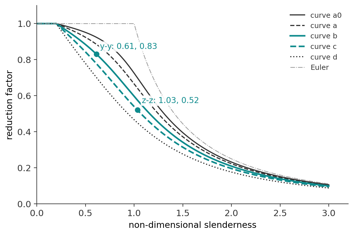
The two codes are doing the same thing with different notation: \(\bar\lambda\) in Eurocode is \(\lambda_n / (\pi\sqrt{E/250}) \approx \lambda_n / 88.9\) with \(E = 200\) GPa, and \(\alpha_c\) plays the role of \(\chi\).
Worked example: HEB 200 in S355 to Eurocode 3
A braced-frame column 4.0 m between floor levels, pinned at both ends about both axes, carries \(G_k = 400\) kN and \(Q_k = 250\) kN from the floors above. Trial section HEB 200 in S355 (\(f_y = 355\) MPa for \(t \le 16\) mm), \(E = 210\) GPa.
Section properties: \(h = b = 200\) mm, \(t_f = 15\) mm, \(t_w = 9\) mm, \(r = 18\) mm, \(A = 7808\) mm\(^2\), \(I_y = 5696 \times 10^4\) mm\(^4\), \(I_z = 2003 \times 10^4\) mm\(^4\).
1. Design load
$$ N_{Ed} = 1.35 \times 400 + 1.5 \times 250 = 915\ \text{kN} $$
2. Classification
\(\varepsilon = \sqrt{235/355} = 0.814\). Flange outstand \(c = (200 - 9 - 2 \times 18)/2 = 77.5\) mm, \(c/t_f = 5.2 \le 9\varepsilon = 7.3\). Web \(c = 200 - 2 \times 15 - 2 \times 18 = 134\) mm, \(c/t_w = 14.9 \le 33\varepsilon = 26.9\). Class 1, so the gross area applies.
3. Section capacity
$$ N_{c,Rd} = \frac{7808 \times 355}{1.0} = 2772\ \text{kN} \ge 915\ \text{kN} $$
4. Buckling about the strong axis (y-y)
\(L_{cr} = 4000\) mm. \(h/b = 1.0 \le 1.2\), \(t_f \le 100\) mm: curve b, \(\alpha = 0.34\).
$$ N_{cr,y} = \frac{\pi^2 \times 210\times10^3 \times 5696\times10^4}{4000^2} = 7379\ \text{kN}, \qquad \bar\lambda_y = \sqrt{\frac{2772}{7379}} = 0.613 $$
$$ \Phi_y = 0.5[1 + 0.34(0.613 - 0.2) + 0.613^2] = 0.758, \qquad \chi_y = \frac{1}{0.758 + \sqrt{0.758^2 - 0.613^2}} = 0.831 $$
$$ N_{b,Rd,y} = 0.831 \times 2772 = 2302\ \text{kN} $$
5. Buckling about the weak axis (z-z)
Curve c, \(\alpha = 0.49\).
$$ N_{cr,z} = \frac{\pi^2 \times 210\times10^3 \times 2003\times10^4}{4000^2} = 2595\ \text{kN}, \qquad \bar\lambda_z = \sqrt{\frac{2772}{2595}} = 1.034 $$
$$ \Phi_z = 0.5[1 + 0.49(1.034 - 0.2) + 1.034^2] = 1.238, \qquad \chi_z = \frac{1}{1.238 + \sqrt{1.238^2 - 1.034^2}} = 0.521 $$
$$ N_{b,Rd,z} = 0.521 \times 2772 = 1443\ \text{kN} \ge 915\ \text{kN} $$
The weak axis governs, at a utilisation of 0.63. The column carries only 52 percent of its squash load because of weak-axis buckling, which is typical for a 4 m storey. Restraining the weak axis at mid-height would lift \(\chi_z\) well above \(\chi_y\) and let the strong axis govern instead.
The same column to AS 4100
For comparison, with \(r_z = \sqrt{2003\times10^4 / 7808} = 50.6\) mm, \(k_f = 1\) and \(\alpha_b = 0\) for a hot-rolled I-section: \(\lambda_n = (4000/50.6)\sqrt{355/250} = 94.1\), and the AS 4100 expressions give \(\alpha_c = 0.581\) against \(\chi_z = 0.521\). AS 4100 then applies \(\phi = 0.9\), so \(\phi N_c = 0.9 \times 0.581 \times 2772 = 1450\) kN, almost identical to \(N_{b,Rd,z} = 1443\) kN. The curves differ, the safety factors sit in different places, and the answers agree within half a percent.
Run it in CalcTree
The column check is a short chain of formulas on section properties, so it can be built as a live, checkable CalcTree page with the section, length and restraints as inputs and the governing axis reported. Start from the Steel Member Design to AS 4100 template or the Steel Section Designer to Eurocode 3. For the bending side of the same members, see steel beam design.





