
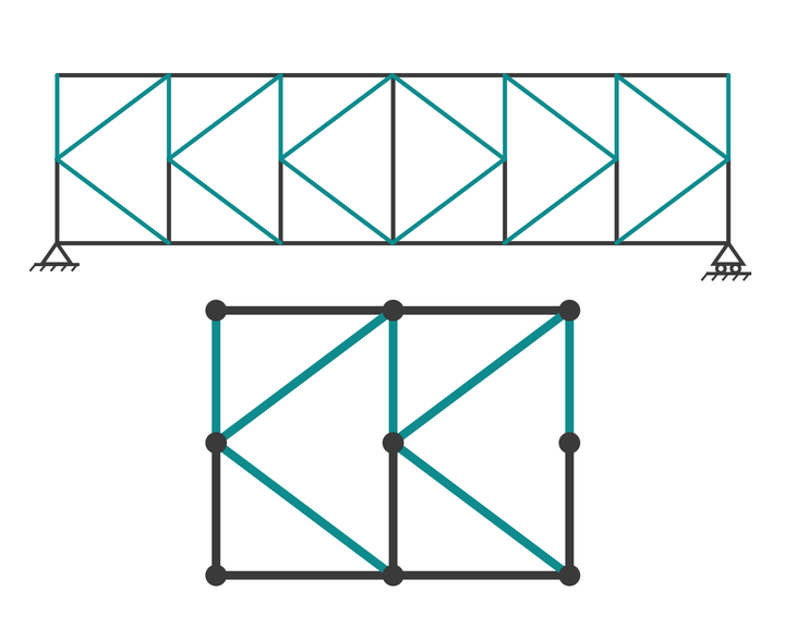
How a K-truss works, why each K has one tension and one compression diagonal, and a worked six-panel example solved by joints and sections.
The K-truss is a parallel-chord truss in which each panel's bracing forms a letter K: a full-height vertical, with two diagonals running from its mid-point to the top and bottom chord joints of the neighbouring panel. Splitting each panel's shear between two short diagonals halves their length and their force, which is why the K-truss is the standard form for deep trusses such as long-span steel bridges, tall transmission towers and the bracing bays of industrial buildings.
This guide explains how a K-truss works, solves a six-panel example by the method of joints and the method of sections, and shows which members carry tension and which compression. It assumes you know the basics from our truss analysis and design guide. The simpler Pratt truss and Warren truss pages make a good comparison, because the K-truss is what you reach for when those become too deep.
What is a K-truss?
In a Pratt or Warren truss, each panel has one diagonal spanning the full depth of the truss. As the truss gets deeper, that diagonal gets long, and a long compression diagonal is wasteful because its capacity is set by buckling rather than by material strength. The K-truss solves this by adding a joint at mid-height of each vertical and running two diagonals from that joint to the adjacent chord joints. Each diagonal now spans only half the truss depth.
The pattern is used in both halves of a span with the K's mirrored about mid-span, so that under gravity load the upper diagonal of each K is in compression and the lower one in tension on both sides. The K-truss is best known from steel through-truss bridges of the 1920s to 1940s and from the bracing of latticed towers and masts, where the "K-bracing" name is used for exactly the same geometry.
Static system
The members are treated as pin-ended and weightless, with loads only at joints, so every member carries axial force alone. On a pin and a roller the span has three reaction components, and it is statically determinate when
$$ m + r = 2j $$
where \(m\) is the number of members, \(r\) the number of reaction components and \(j\) the number of joints.
A K-truss has more members and more joints than a Pratt of the same panel count, so it pays to check this before starting. In the example, each of the six verticals carrying a K is split into two members by its mid-height joint, and the centre vertical is a single member. That gives 12 chord members, 13 vertical members and 12 diagonals, \(m = 37\), with \(r = 3\) and \(j = 20\): \(37 + 3 = 40 = 2 \times 20\). The truss is determinate.
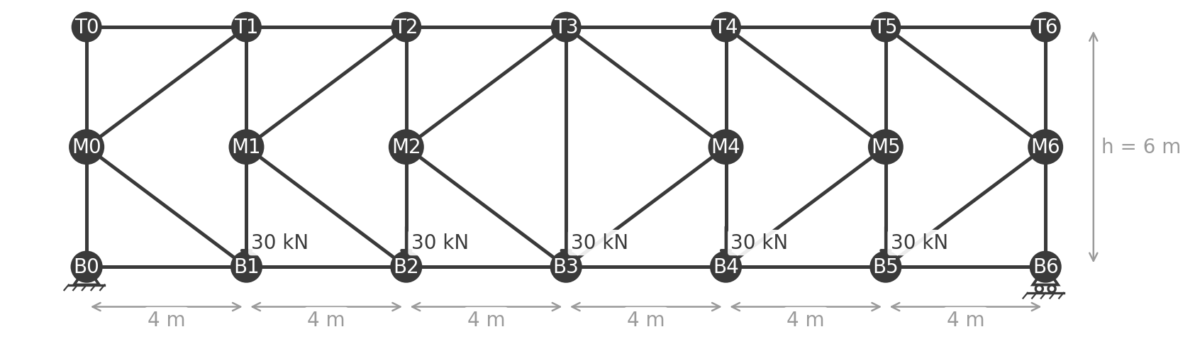
The example spans 24 m in six panels of 4 m and is 6 m deep, so the mid-height joints sit at 3 m and each diagonal is a 3-4-5 triangle: 5 m long, with \(\sin\theta = 0.6\) and \(\cos\theta = 0.8\). The K's open toward mid-span, with the end posts also carrying a K. The deck is on the bottom chord and delivers 30 kN to each of the five interior bottom chord joints.
K-truss analysis
Every number in this section can be reproduced in the truss analysis calculator: choose K, a 24 m span, 6 m depth, six panels and 30 kN on the bottom chord, and read the reactions and member forces off the page.
Reaction forces
The total load is \(5 \times 30 = 150\) kN, symmetric about mid-span, so
$$ R_A = R_B = \frac{150}{2} = 75 \text{ kN} $$
The key to the K: the mid-height joint
What makes the K-truss tractable by hand is horizontal equilibrium at the mid-height joint. Four members meet there: the two halves of the vertical, which are vertical and contribute nothing horizontally, and the two diagonals, which have equal and opposite horizontal components only if their forces are equal and opposite. With no horizontal load at the joint,
$$ F_{upper} \cos\theta + F_{lower} \cos\theta = 0 \quad\Rightarrow\quad F_{upper} = -F_{lower} $$
So in every K, one diagonal is in tension and the other in compression, with the same magnitude. Vertical equilibrium at the same joint then says the two diagonals' vertical components add, and the difference between the forces in the upper and lower halves of the vertical equals that sum.
Method of joints
At the support joint B0, the reaction of 75 kN is balanced by the lower half of the end post, so \(F_{B0M0} = -75\) kN (compression), and with nothing else horizontal, \(F_{B0B1} = 0\). At the top joint T0 there is no load and only two perpendicular members, so \(F_{M0T0} = 0\) and \(F_{T0T1} = 0\).
At the mid-height joint M0 the end post pushes up with 75 kN, and the two diagonals M0T1 and M0B1 are equal and opposite. With tension positive, vertical equilibrium gives
$$ 75 + F_{M0T1} \sin\theta - F_{M0B1} \sin\theta = 0 $$
and substituting \(F_{M0B1} = -F_{M0T1}\):
$$ 75 + 2 F_{M0T1} \times 0.6 = 0 \quad\Rightarrow\quad F_{M0T1} = -62.5 \text{ kN}, \quad F_{M0B1} = +62.5 \text{ kN} $$
The upper diagonal is in compression and the lower one in tension, and each carries half the panel shear divided by \(\sin\theta\): \(75 / (2 \times 0.6) = 62.5\) kN.
At T1, the upper diagonal M0T1 pushes up with a vertical component of \(62.5 \times 0.6 = 37.5\) kN, which the upper half of the vertical must hold down: \(F_{M1T1} = +37.5\) kN, tension. At B1, the lower diagonal M0B1 pulls up with 37.5 kN against the 30 kN load, so the lower half of the vertical pushes down with the 7.5 kN difference: \(F_{B1M1} = -7.5\) kN, compression. The two halves of the same vertical carry different forces, which is the second thing that distinguishes the K-truss from a Pratt.
Method of sections
Cut the truss through the second panel. The cut crosses four members, T1T2, M1T2, M1B2 and B1B2, which is one more than the three equilibrium equations can handle, so the method needs the mid-joint result from above: \(F_{M1T2} = -F_{M1B2}\).
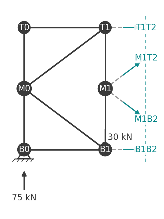
With the diagonals equal and opposite, their horizontal components cancel and horizontal equilibrium of the free body gives \(F_{T1T2} = -F_{B1B2}\): the chord forces are also equal and opposite. Moments about the mid-height joint M1, through which both diagonals pass, then give the chords directly:
$$ F_{B1B2} \times 3 - F_{T1T2} \times 3 = 75 \times 4 \quad\Rightarrow\quad 2 F_{B1B2} \times 3 = 300 $$
$$ F_{B1B2} = \frac{300}{6} = 50 \text{ kN}, \qquad F_{T1T2} = -50 \text{ kN} $$
which is the bending moment at the K's vertical divided by the full truss depth, exactly as for any parallel-chord truss. Vertical equilibrium of the free body gives the diagonals:
$$ 75 - 30 + F_{M1T2} \sin\theta - F_{M1B2} \sin\theta = 0 \quad\Rightarrow\quad 45 + 2 F_{M1T2} \times 0.6 = 0 $$
$$ F_{M1T2} = -37.5 \text{ kN}, \qquad F_{M1B2} = +37.5 \text{ kN} $$
Each diagonal carries half of the 45 kN panel shear, divided by \(\sin\theta\). The pattern holds across the span: diagonal force is \(V / (2 \sin\theta)\) and chord force is \(M / h\).
Compression and tension members
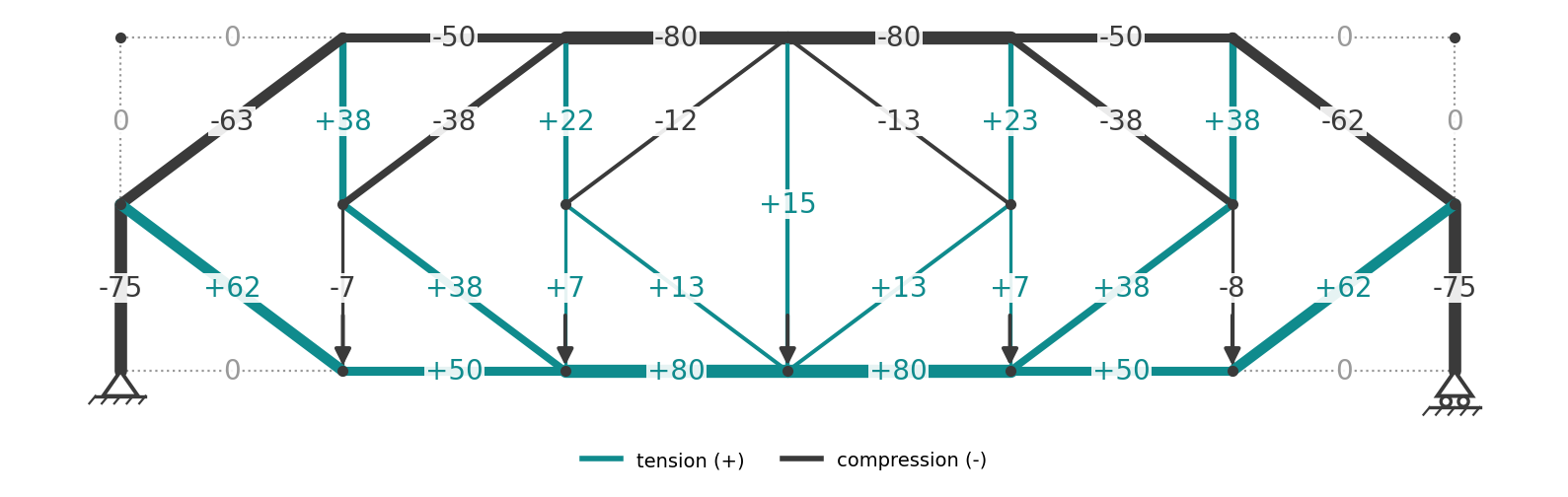
The full set of member forces, with tension positive:
- Bottom chord: 0, 50, 80, 80, 50, 0 kN, tension.
- Top chord: 0, 50, 80, 80, 50, 0 kN, compression. The 80 kN peak is at mid-span.
- Upper diagonals, from the support inward: 62.5, 37.5, 12.5 kN, compression. Lower diagonals: the same values in tension. Mirrored on the right.
- Verticals: end posts 75 kN compression in the lower half and zero above; the vertical at B1 is 37.5 kN tension above the K joint and 7.5 kN compression below; at B2 it is 22.5 kN tension above and 7.5 kN tension below; the centre vertical carries 15 kN tension.
Compared with a Pratt truss of the same span and loads but half the depth, the chord forces here are halved because the depth is doubled, and the diagonal forces are halved because two diagonals share each panel's shear. The compression diagonals are 5 m long rather than the 7.2 m a single full-depth diagonal would be, which roughly halves their buckling length and cuts the required section substantially. The steel bracing guide covers the same reasoning for K-bracing in building frames.
Member design and code references
- Compression diagonals and chords: EN 1993-1-1 clause 6.3.1, \(N_{b,Rd} = \chi A f_y / \gamma_{M1}\). AS 4100 clauses 6.2 and 6.3, \(N_s = k_f A_n f_y\) and \(N_c = \alpha_c N_s\). The in-plane effective length of a K diagonal is its own 5 m length; out of plane it depends on whether the mid-height joint is restrained.
- Tension diagonals and bottom chord: EN 1993-1-1 clause 6.2.3; AS 4100 clause 7.2, including the \(k_t\) reduction for eccentrically connected angles.
- Load combinations: EN 1990 or AS/NZS 1170.0. Bridge traffic loads from EN 1991-2 or AS 5100.2.
Because the two halves of each vertical carry different forces, and the diagonals reverse sign under a moving load, a K-truss member schedule lists more distinct cases than a Pratt. The steel member design to AS 4100 page runs the tension and compression capacities for any trial section so each case can be checked quickly.
Advantages and disadvantages
Advantages:
- Short diagonals, so deep trusses are possible without long compression members.
- Each panel's shear is shared by two diagonals, halving the force in each.
- Deep trusses mean low chord forces and stiff spans, which suits long bridges and tall towers.
- The mid-height joint provides a natural restraint point for the vertical.
Disadvantages:
- Roughly twice as many diagonals and 50 per cent more joints than a Pratt, so fabrication and connection cost is higher.
- Hand analysis needs the mid-joint trick; a naive section cut has four unknowns.
- The visual complexity makes it an unusual choice where appearance matters.
K-truss FAQ
What is the advantage of a K-truss over a Pratt truss?
Shorter diagonals carrying half the force each. For a deep truss the Pratt's single full-depth compression diagonals become long and buckling-limited; the K halves their length.
Why are the diagonals in a K-truss equal and opposite?
Because the mid-height joint has no horizontal load and the only members with horizontal components there are the two diagonals. Horizontal equilibrium forces their horizontal components, and so their forces, to be equal and opposite.
Is a K-truss statically determinate?
Yes, when the K's are arranged so that \(m + r = 2j\) holds, as in the example. A section cut through a panel crosses four members, so the method of sections alone cannot solve it; you combine it with joint equilibrium at the mid-height joint.
Where is the K-truss used today?
Latticed transmission towers and masts, bracing bays in industrial steel buildings, deep steel bridges and crane girders. In towers it is usually called K-bracing.
Run it in CalcTree
The truss analysis calculator runs this example live, and switches between the Warren, Pratt, Howe and K forms on the same span. The joint and section equations above are a small, repeatable set that can be built as a live CalcTree page: panel count, panel length, depth and joint loads in, every member force out, with the governing compression diagonal flagged. Connect the forces to the AS 4100 steel member check to size each member, or browse the template library for the Eurocode 3 version.





