Analyse bolt groups per AS 4100 using the ICR method. Check single-bolt and group capacities for in- and out-of-plane loads with engineering-grade outputs.

This template is not available yet. You can sign up and create it yourself!
Or let us know if you'd like to be notified when it’s ready:
No items found.
No items found.
About this Bolt Group Calculator
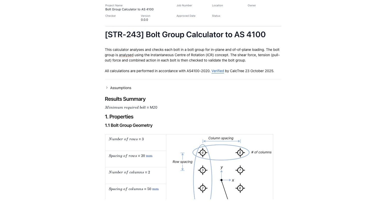
This engineering-grade tool analyses a bolt group and checks each bolt for in-plane and out-of-plane actions per AS 4100:2020. Resultant shear, tension (pull-out) and combined action are calculated using the Instantaneous Centre of Rotation (ICR) method, then compared against single-bolt and group capacities.
- Structural engineer: size bolts and verify splice/connection details in steel frames against AS 4100 using transparent calcs and tables.
- Connection/detailing engineer: iterate bolt layouts, spacings and grades, and export a clean report for checking and issue.
- Engineering manager/QC: standardise connection checks across teams and lock compliance to AS 4100.
Use it as a ready-to-run template or duplicate and adapt it to your standard details. Results are traceable with geometry plots, centroid, second moments (Ix, Iy, Ip) and per-bolt force tables.
More on this Bolt Group Analysis to AS 4100 tool
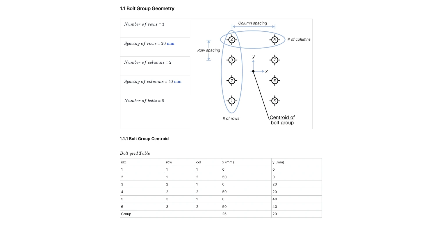
Geometry & Centroid
Define the bolt grid using rows, columns, and their spacings. The template plots the layout, labels axes, and auto-builds a bolt table with each bolt’s coordinates. From this, the group centroid is calculated and used as the reference for resolving all actions.
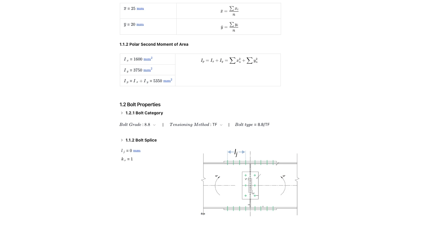
Second Moments for ICR Distribution
The calculator determines the group second moments about the principal axes and the polar second moment. These stiffness terms feed the Instantaneous Centre of Rotation method so rotational components are apportioned to each bolt consistently with AS 4100 practice.
Bolt Category & Joint Parameters
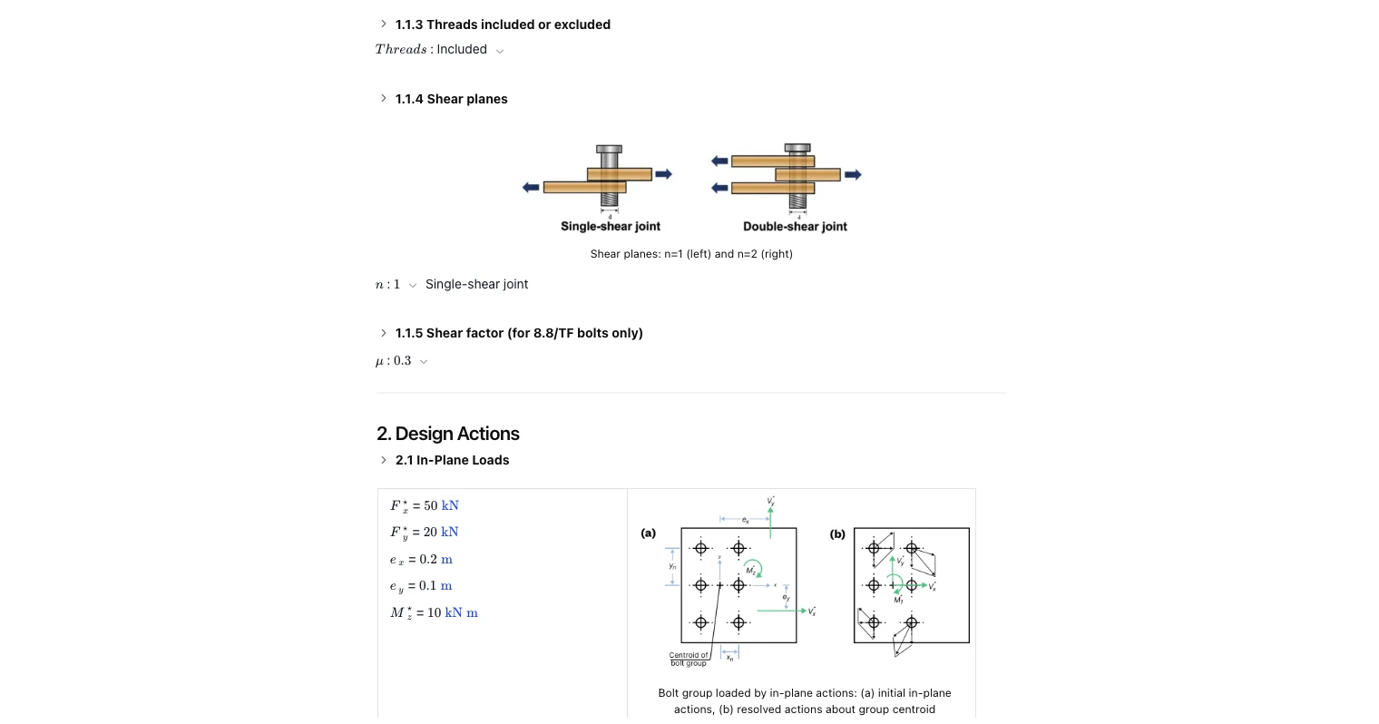
Select bolt grade/category, tensioning method, thread condition (included/excluded), and the number of shear planes (single or double). Splice-related inputs (such as joint length and reduction factors) are included. These choices drive the single-bolt capacity table used in the checks.
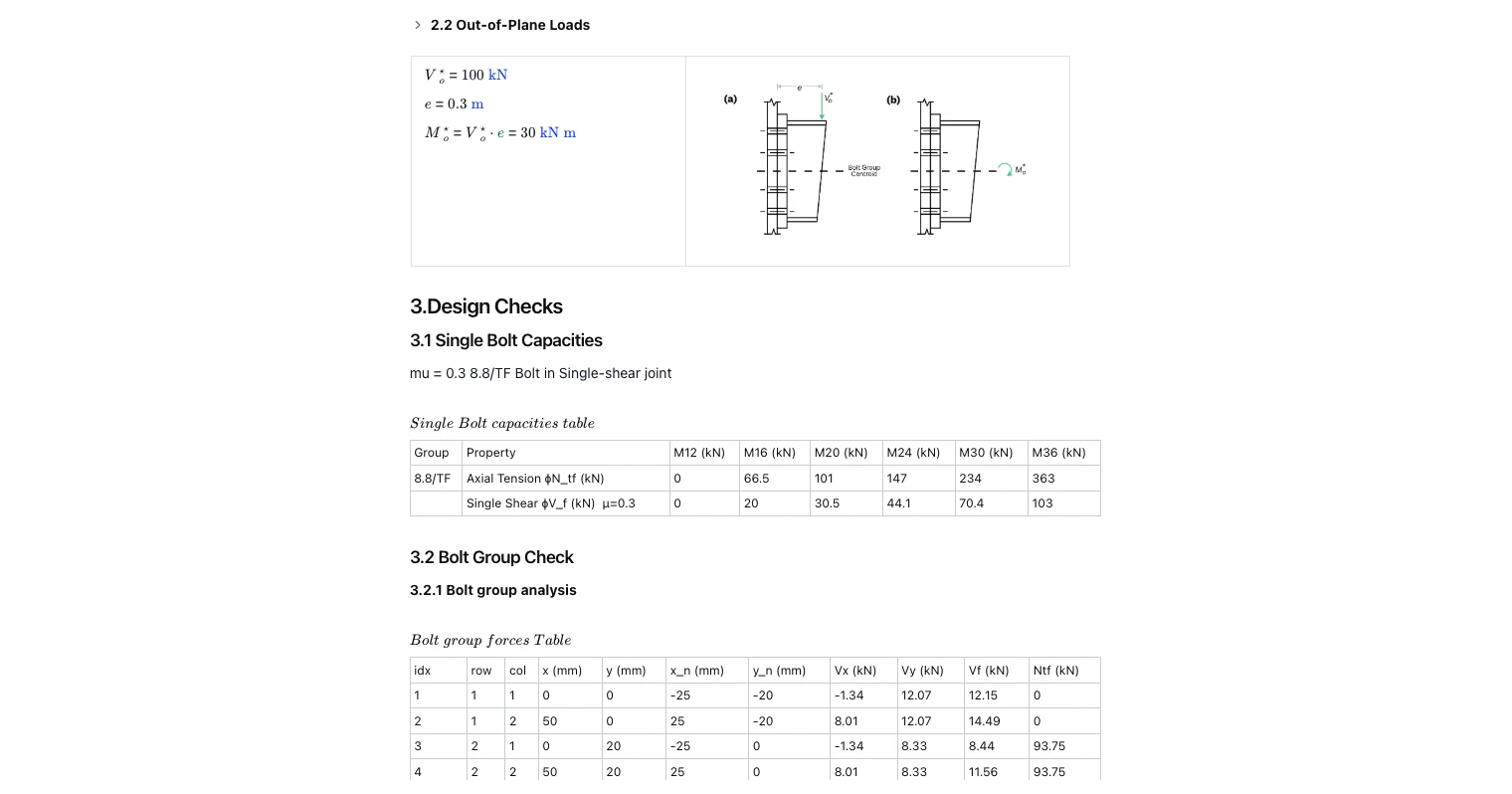
Actions: In-Plane and Out-of-Plane
Enter in-plane shear components with any eccentricities and/or a moment about the plate, and—if relevant—out-of-plane shear with its eccentricity. The tool resolves loads about the centroid, shows clear schematics, and forms the resulting moments used in the ICR analysis.
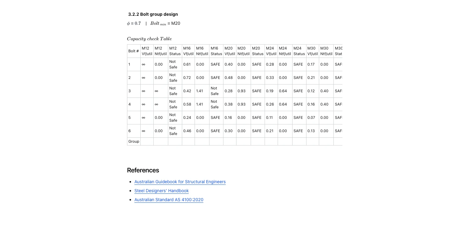
Per-Bolt Forces, Utilisation & Minimum Size
Results are presented in a per-bolt force table (shear components, resultant, and tension) followed by a capacity-check table across common diameters. Status flags (safe/not safe) are shown for each size, and the template reports the minimum compliant bolt size for the given inputs.
Common Calculation Errors to Avoid
- Wrong bolt category or tensioning method: 8.8/TF vs 8.8/S changes capacity rules and μ applicability.
- Incorrect thread assumption: threads included/excluded affects shear/bearing capacities in an AS 4100 bolt calculator.
- Mis-setting shear planes n: single vs double shear drastically changes design strength.
- Mixing units for geometry/actions: mm vs m on spacings or eccentricities skews Ix/Iy/Ip and ICR results.
- Forgetting to resolve about the centroid: ICR distribution assumes centroid-based actions.
- Applying friction factor outside scope: μ = 0.3 shown is for TF bolts under slip-resistance; don’t generalise.
- Ignoring the reported minimum size: the summary may indicate M20 (as shown); don’t overlook it in detailing.
Engineering templates
Common calculators
Design guides
FAQs
What inputs does the calculator need?
Bolt grid (rows, columns, spacings), bolt grade/category, thread condition, number of shear planes, splice length and load set (Vx, Vy, Mz and/or out-of-plane V with eccentricity). The tool then computes centroid, Ix/Iy/Ip, ICR location, per-bolt forces and capacity checks.
How does it pick the minimum bolt size?
After computing per-bolt demand via ICR, the tool checks against tabulated single-bolt capacities for common diameters (e.g., M12–M36). It then reports the smallest diameter meeting φ-factored AS 4100 requirements.
Does it handle out-of-plane loading?
Yes. Provide the out-of-plane shear and eccentricity; the tool resolves the resulting moment and includes it in the ICR distribution and capacity checks.
Can I customise grades or spacings?
Yes. Duplicate the template, adjust inputs (spacings, bolt grade, μ, n, threads) and rerun. You can also add your own notes and download the report as a PDF.


Learn about the benefits of using CalcTree on engineering projects!