Free Fillet Weld Group Analysis Design Tool to AS 4100:2020. Step-by-step, engineering-grade tool with downloadable report.

This template is not available yet. You can sign up and create it yourself!
Or let us know if you'd like to be notified when it’s ready:
No items found.
No items found.
About this Fillet Weld Group Calculator
The Fillet Weld Group Analysis to AS 4100 tool is an online technical report creation tool designed to streamline the analysis of fillet welds in weld groups subjected to in-plane loading. It leverages the Instantaneous Center of Rotation (ICR) concept to accurately evaluate the forces within each fillet weld, ensuring the design shear at critical points is checked against AS 4100:2020 standards. It locates the weld group centroid, resolves direct and moment-induced shear along each weld line, and checks demand vs capacity at weld ends.
- Structural Engineers: Ensure compliance with AS 4100 standards, and automate the calculation of weld forces without spinning up a full FEA model
- Construction Professionals: Expedite the verification of weld group strength, especially when considering shear forces in structural components.
- Civil Engineering Students: Gain practical insight into the design and analysis of weld groups through real-world applications based on Australian standards.
It’s an engineering-grade calculator with transparent equations, tabulated geometry, and line-by-line pass/fail checks.
More info on Fillet Weld Group Calculator
Inputs
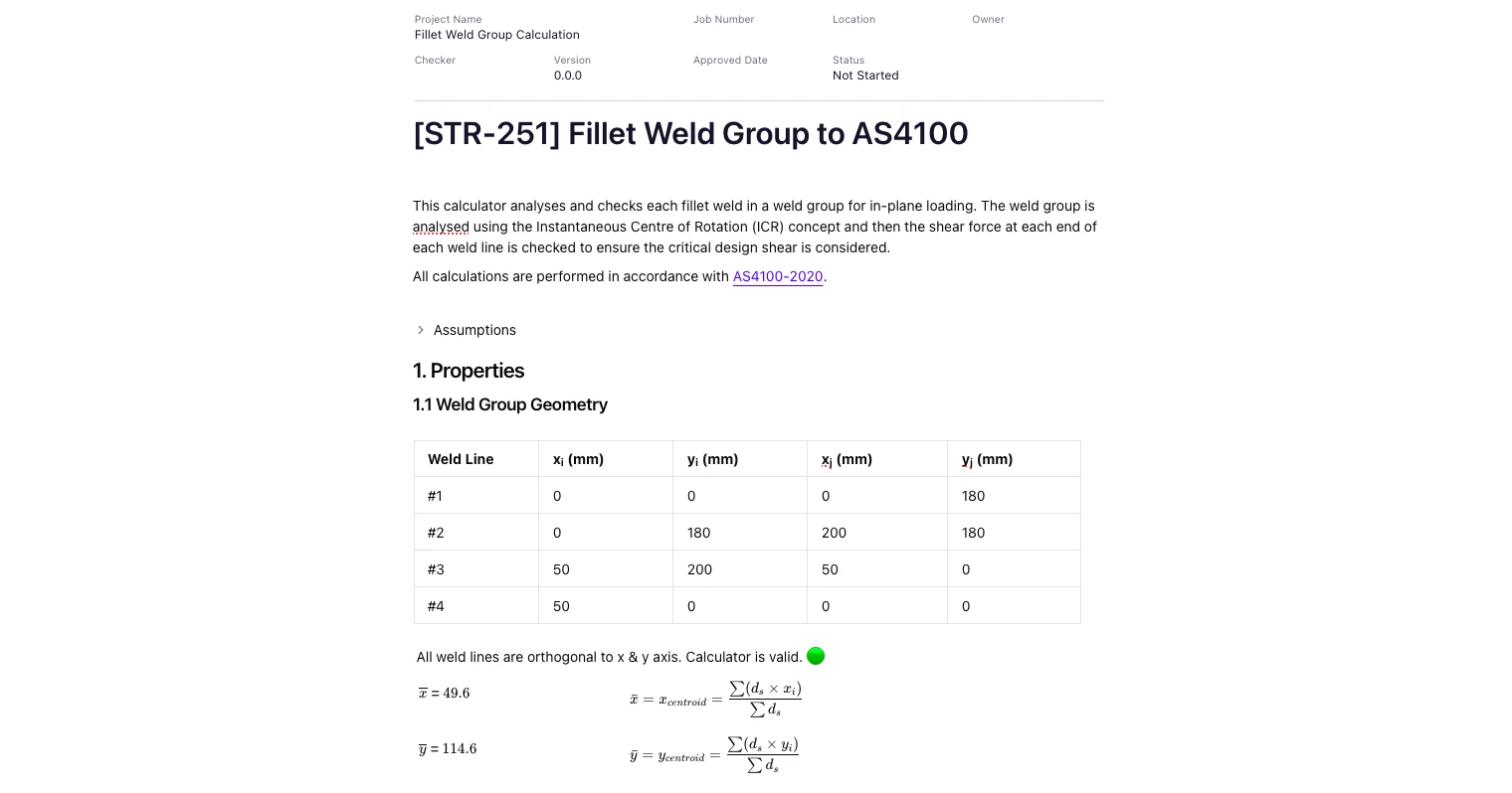
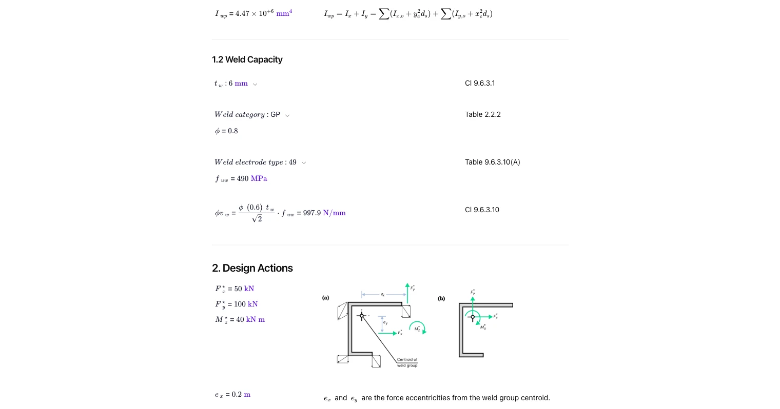
Define weld line geometry in a simple table: start/end coordinates for each weld segment relative to a common origin. Provide weld size, weld category, electrode type/strength, and the AS 4100 capacity factor. Enter design actions as in-plane shear components and any in-plane moment about the centroid. The tool also accepts eccentricities to convert applied forces to centroidal actions.
Method (ICR and section properties)
The calculator checks orthogonality of weld lines, finds the centroid of the group, and computes the group’s second moments about the centroid plus the polar quantity required for ICR-based shear distribution. Using AS 4100 notation, direct shear from forces is combined with shear from the moment using distances from each point to the centroid.
Design actions resolution
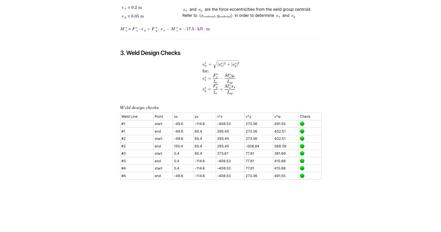
Applied forces are resolved to the weld group centroid. Eccentricities about each axis are used to form an equivalent moment. For each weld line end (start/end), the calculator determines local shear components due to force and moment and then combines them vectorially to a resultant design shear per unit length.
Outputs and pass/fail checks
You’ll get:
- Centroid coordinates of the weld group and the relevant second-moment/polar properties
- Unit design shear at each weld end (components and resultant)
- Design shear capacity per unit length based on weld size, category and electrode strength per AS 4100
- A pass/fail indicator for each line end with a summary table suitable for reports
Common Calculation Errors to Avoid
- Mixing coordinate signs or origins, leading to incorrect distances to the centroid and wrong moment-induced shear.
- Assuming non-orthogonal weld lines are valid, when the ICR method here expects weld segments aligned to x/y axes.
- Using leg size instead of effective throat, which overstates capacity for fillet welds in AS 4100 checks.
- Confusing electrode strength grades, resulting in an incorrect unit shear capacity for the weld metal.
- Forgetting capacity factors (phi), which must reflect the AS 4100 weld category and limit state.
- Mixing units (N/mm vs kN and mm), which silently skews both demand and capacity in a weld group calculator.
- Applying moments about the wrong point, rather than first resolving actions to the weld group centroid.
Engineering templates
Common calculators
Design guides
FAQs
How does the calculator distribute shear from a moment in a weld group?
It applies the ICR method from AS 4100. The moment about the centroid generates shear proportional to the distance of each weld point from the centroid, combined with direct shear from applied forces to give a resultant unit shear.
What geometry do I need to define?
Provide start/end coordinates for each weld line in a single table. The tool calculates the centroid and section properties automatically and then evaluates both ends of every segment.
Does it check each end of a weld line?
Yes. Both start and end points are checked because the combined shear can peak at different ends depending on load directions and eccentricities.
Which AS 4100 clauses are referenced?
Capacity and detailing follow AS 4100 provisions for fillet welds (including category, electrode type, capacity factor, and unit shear capacity expressions). Clause and table references are shown alongside each step in the template.
Can this handle out-of-plane loading?
This template is for in-plane loading of fillet weld groups. For out-of-plane or combined three-dimensional effects, use a suitable 3D connection model or a dedicated template.
Where can I try or duplicate the calculator?
Click on 'Use template' to get started. You can also add other engineering templates and stitch them into your workflow on CalcTree.


Learn about the benefits of using CalcTree on engineering projects!