Engineer-grade reinforced concrete column calculator to AS 3600. Build P-M interaction diagrams, design checks and minimum moments in minutes on CalcTree.

This template is not available yet. You can sign up and create it yourself!
Or let us know if you'd like to be notified when it’s ready:

No items found.
No items found.
About this Concrete Column Design to AS 3600 Calculator
This template builds the axial-moment interaction curve for a reinforced concrete column and checks combined actions to AS 3600:2018. It covers materials, geometry, reinforcement, design actions and the full P-M diagram for both principal axes.
- Structural engineer: size and check rectangular RC columns under axial load with biaxial bending using AS 3600 clause logic and capacity reduction factors.
- Design checker/peer reviewer: verify inputs, minimum moments and plotted capacities against the governing clauses with clear maths notation.
- Digital/automation lead: standardize a repeatable, auditable column design workflow that your team can duplicate and adapt inside CalcTree.
The calculator is engineering-grade: variables are unit-aware, equations are transparently shown, and each step references AS 3600 clauses used in the capacity calculations. Use and customise to suit your teams requirements.
For an in-depth guide on column design to Australian Standards, check out our Concrete Column Design Guide.
Introduction to Concrete Column Design to AS 3600 Calculations
Materials Inputs
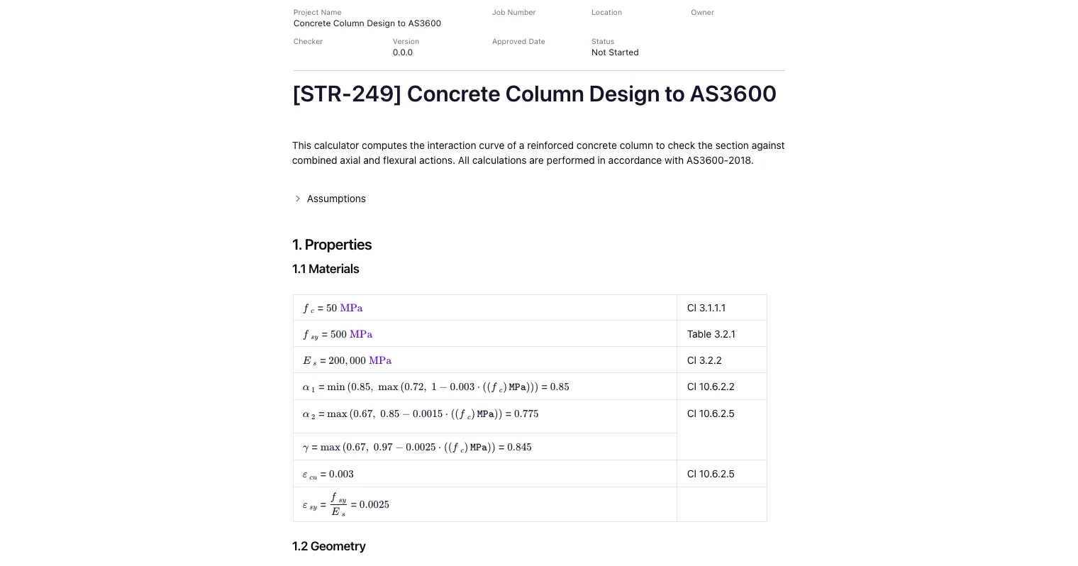
Define concrete strength, steel grade and elastic modulus. Stress-block parameters (α1, α2, γ) are computed per AS 3600 and limited to the code bounds. Ultimate steel and concrete strains are included for section analysis, and capacity reduction factors (ϕ) are applied per the limit state being checked.
(See “1.1 Materials” in the screenshots.)
Geometry & Reinforcement Inputs
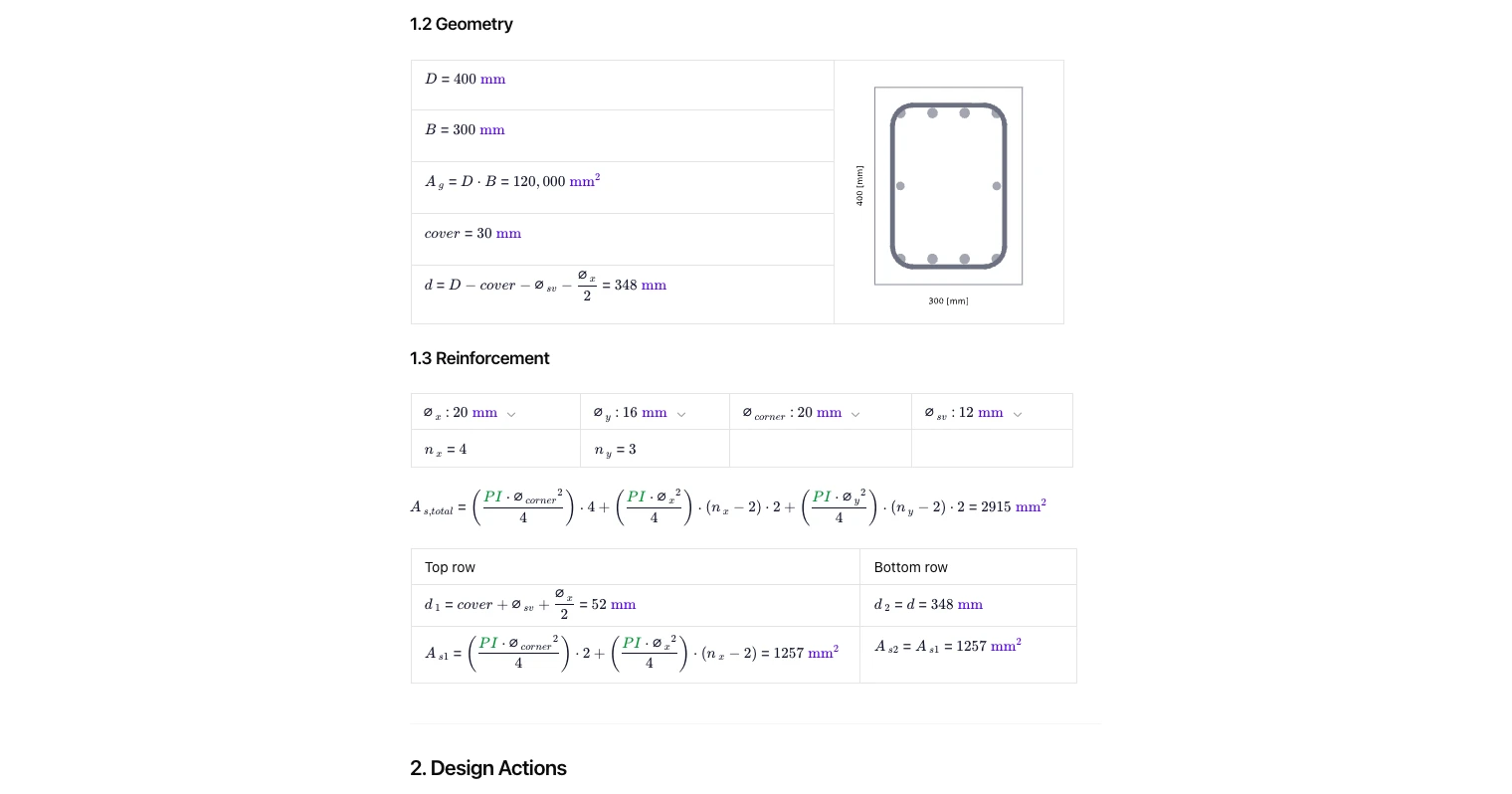
Set overall section dimensions, cover and effective depth. Choose bar diameters for the x-row, y-row and corner bars, plus ties. The tool totals bar count and steel area and derives layer depths used in force and moment summations about each axis.
(See “1.2 Geometry” and “1.3 Reinforcement”.)
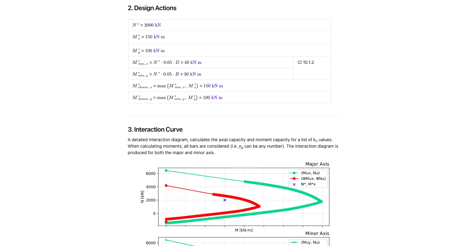
Design Actions and Minimum Moments
Enter the factored axial load N* and bending actions Mx*, My*. The calculator enforces the minimum eccentricity moments required by AS 3600 (e.g., clause 10.1.2) so that very small moments are not overlooked. The governing design actions for each axis are then carried through to the interaction check.
(See “2. Design Actions”.)
Interaction Diagram Method (A–E Points)
The calculator constructs the P-M diagram for major and minor axes using standard reference points:
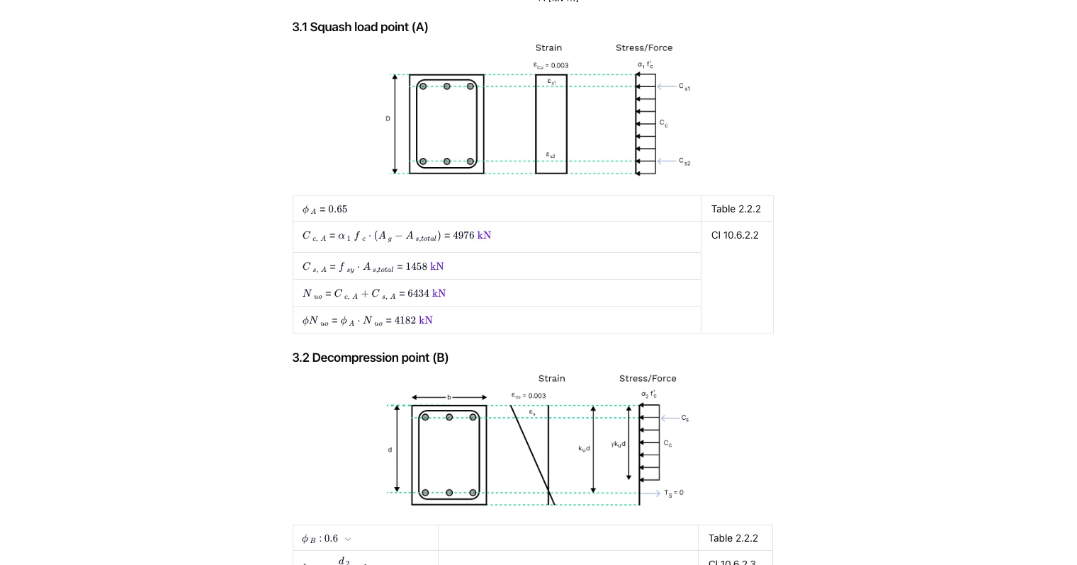
- Squash load (A): concrete compression block with confined steel contribution and ϕ applied.
- Decompression (B): neutral axis at the tensile face; steel tension initiates; ku and γku d terms derived.
- Balanced (C): simultaneous yielding/ultimate strain condition; forces summed over all bar layers to give Nu, Mu for each axis.
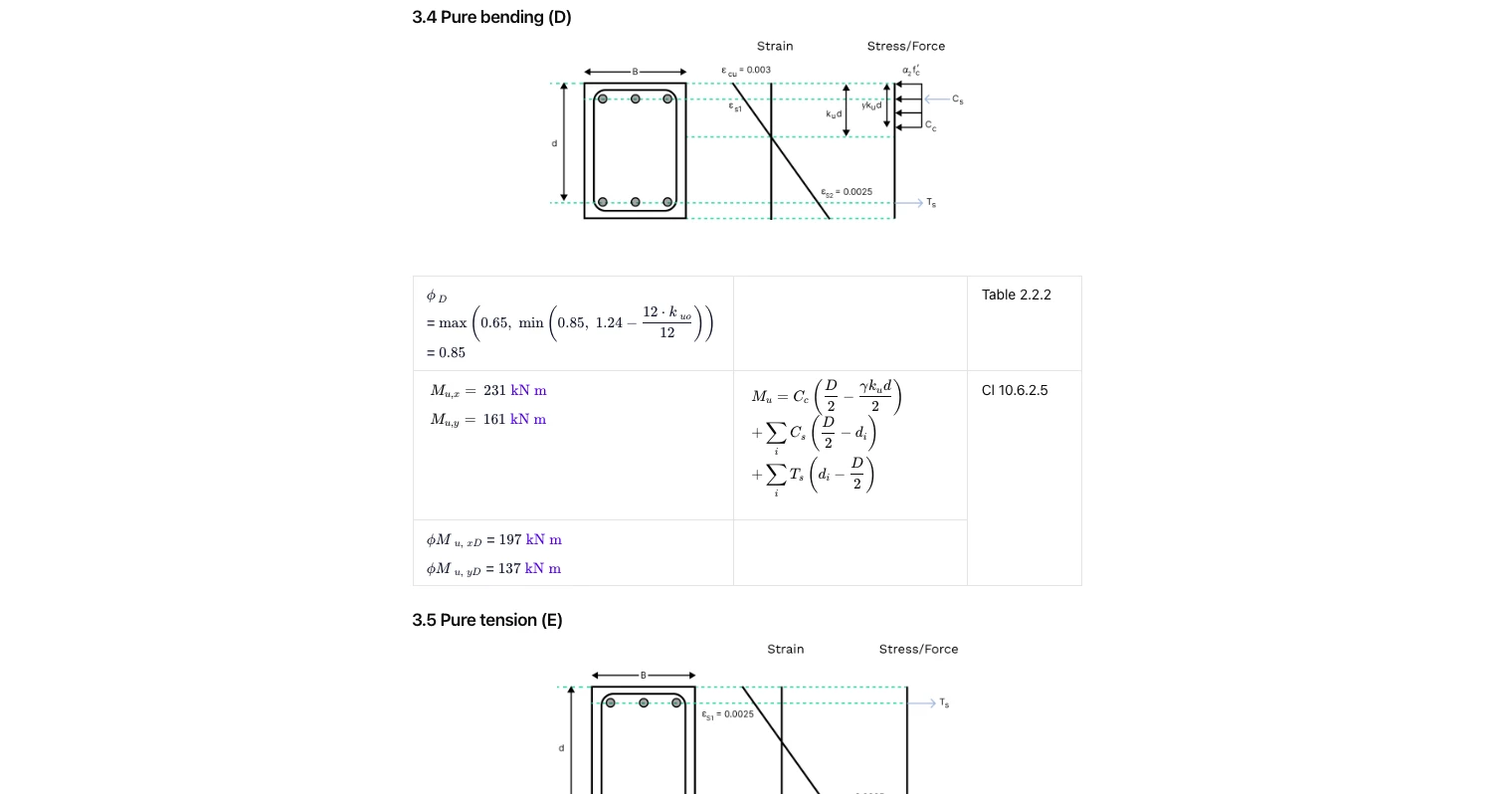
- Pure bending (D): axial force ≈ 0 with capacity reduction per AS 3600; moment taken about each axis using bar lever arms.
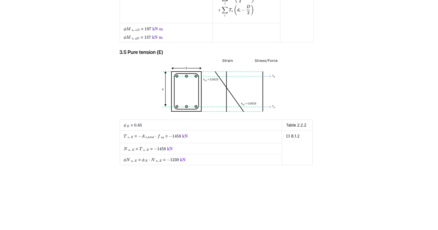
- Pure tension (E): steel controls with tension capacity and corresponding ϕ.
The curve is plotted and the design point is overlaid for pass/fail assessment.
(See “3. Interaction Curve” and subsections 3.1–3.5 in the images.)
Common Calculation Errors to Avoid
- Forgetting minimum moments: not applying AS 3600 minimum eccentricity can falsely show high axial capacity.
- Using gross depth instead of effective depth: neglecting cover and bar diameter offsets the lever arms and Ku location.
- Misplacing bar layers between axes: swapping nx/ny or corner bars changes steel areas and lever arms for Mx and My.
- Mixing units: combining N, mm and MPa inconsistently skews forces and moments; keep inputs unit-consistent.
- Applying the wrong ϕ factor: ensure reduction factors match the specific limit state (compression, bending, tension).
- Ignoring biaxial effects: checking one axis only can miss the true governing interaction.
For further comprehensive information, see our Concrete Column Design Guide.
Engineering templates
Common calculators
Design guides
FAQs
What does the interaction diagram show?
It plots axial capacity against bending capacity for many neutral-axis positions, for both major and minor axes. Your design point (N*, Mx*, My*) is shown on the chart to confirm if it lies within the φ-reduced capacity envelope.
How are minimum moments handled?
The tool automatically computes the code-required minimum moments for each axis and adopts the greater of the entered moment and the minimum per AS 3600. This avoids unconservative near-pure-compression checks.
Can it handle any bar arrangement?
Yes—enter bar diameters and counts in the x-row, y-row and corners. The calculator sums steel areas and uses correct layer depths when forming Cc, Cs and Ts for the moment equilibria about each axis.
Which AS 3600 clauses are referenced?
Key references include stress-block and strain limits, ϕ factors and minimum moment requirements (e.g., Section 10 and associated tables). Each step in the template shows the clause or table used beside the calculation.
What is the squash load for a concrete column?
The squash load represents the theoretical maximum axial load a column can carry under pure compression, before buckling or material failure.
How do interaction diagrams help in column design?
An interaction diagram is a graphical representation of the ultimate strength of a column's cross-section, allowing engineers to confirm whether a column’s combined loading stays within safe limits.
In the Australian Standards, it is defined by four critical points which form the boundary of failure for a section subject to combined bending and axial load. The critical points are called:
- Squash load
- Decompression point
- Balanced point
- Pure bending
Each point on the boundary of an interaction diagram describe a value for the axial capacity and bending capacity for a given reinforcement arrangement based on a specific neutral axis depth.


Learn about the benefits of using CalcTree on engineering projects!