
Analyse a cantilever shear wall with openings in plane stress. A real OpenSees solve plots the stress field to reveal the load path around each opening.

This template is not available yet. You can sign up and create it yourself!
Or let us know if you'd like to be notified when it’s ready:
No items found.
No items found.
Shear wall with openings, analysed in plane stress
A solid cantilever shear wall carries lateral load in a simple way. Bending puts tension up one edge and compression down the other, with a roughly uniform shear field between. Punch a door or a window through it and that stops being true. The wall becomes a set of piers connected by spandrel beams, the load path detours around each opening, and stress concentrates sharply at the opening corners.
Hand methods either ignore the openings or idealise the wall as a coupled-wall frame. This page does neither. It meshes the wall into four-node plane-stress quadrilaterals, removes the elements that fall inside an opening, and analyses the real geometry. Openings are entered as fractions of the wall dimensions, so they scale with the wall rather than needing re-entry every time the geometry changes.
The solve is a real finite element analysis running in the page (OpenSees), not a closed-form idealisation. That means it handles arbitrary geometry entered as a table rather than a fixed standard case, and it returns diagrams and contour plots alongside the numbers.
What the plots show
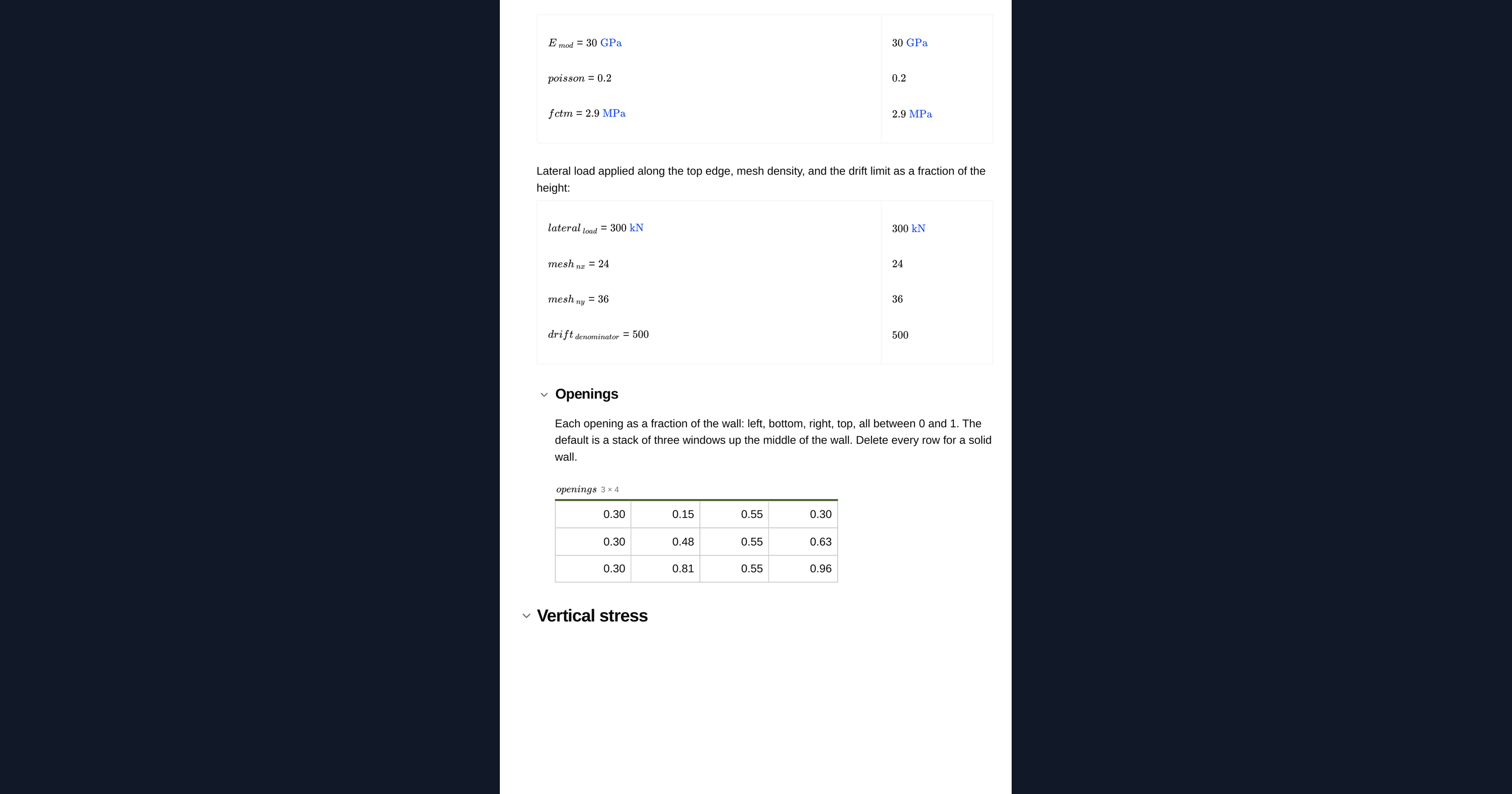
- Vertical stress is the bending action: tension up one edge, compression down the other, redistributed around each opening into the piers.
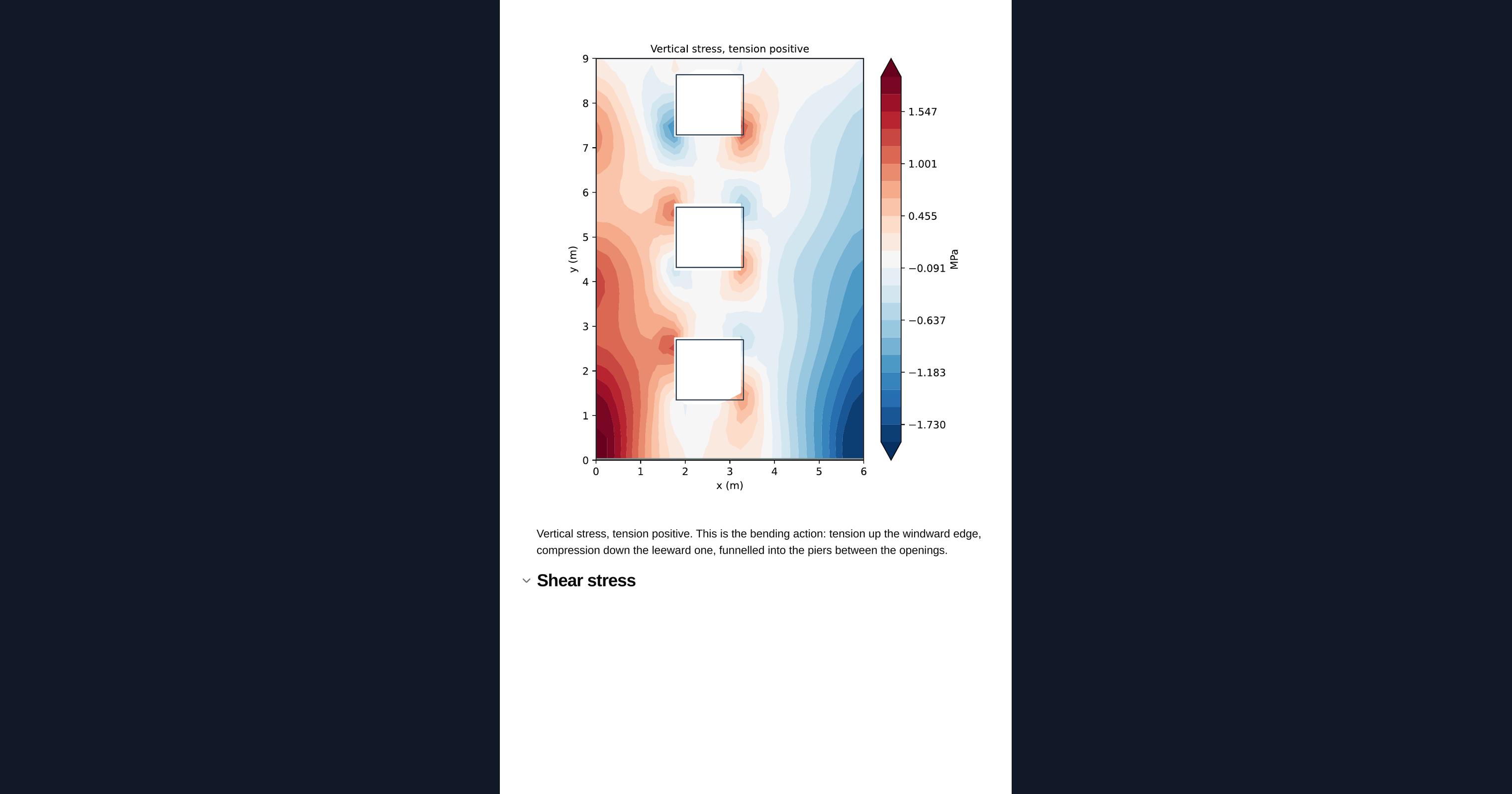
- Shear stress shows how load transfers between piers through the spandrels, which is where a coupled wall does its work.
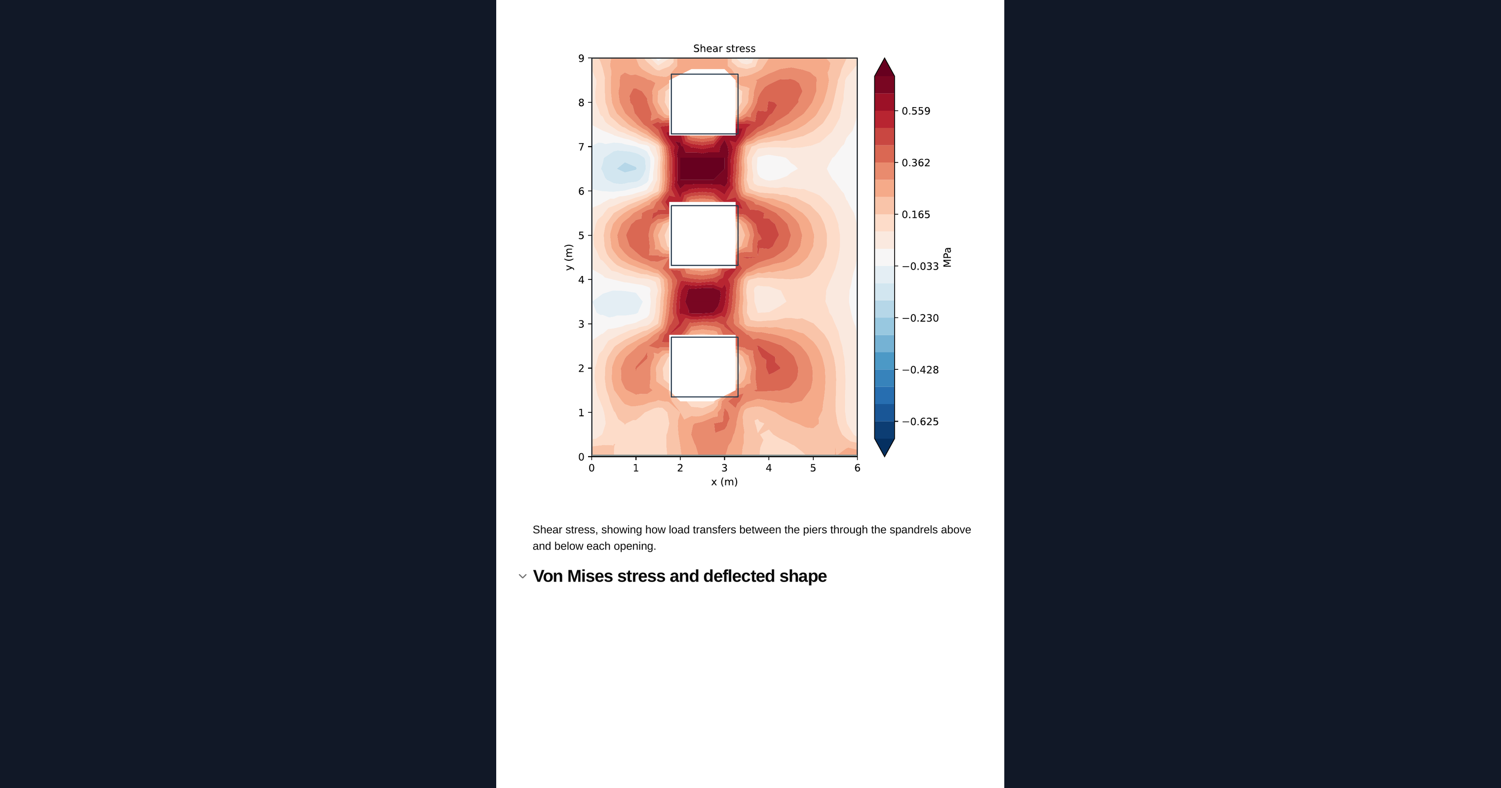
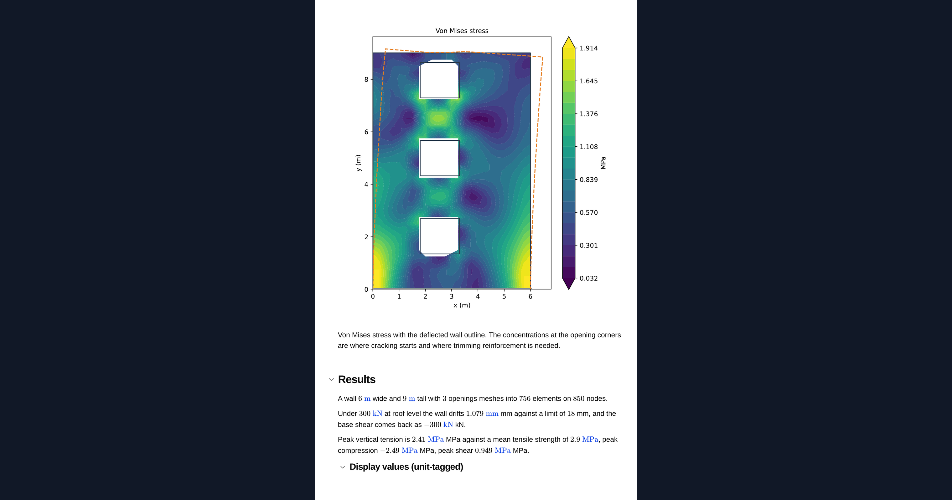
- Von Mises stress locates the concentrations at the opening corners.
Read the equilibrium check first
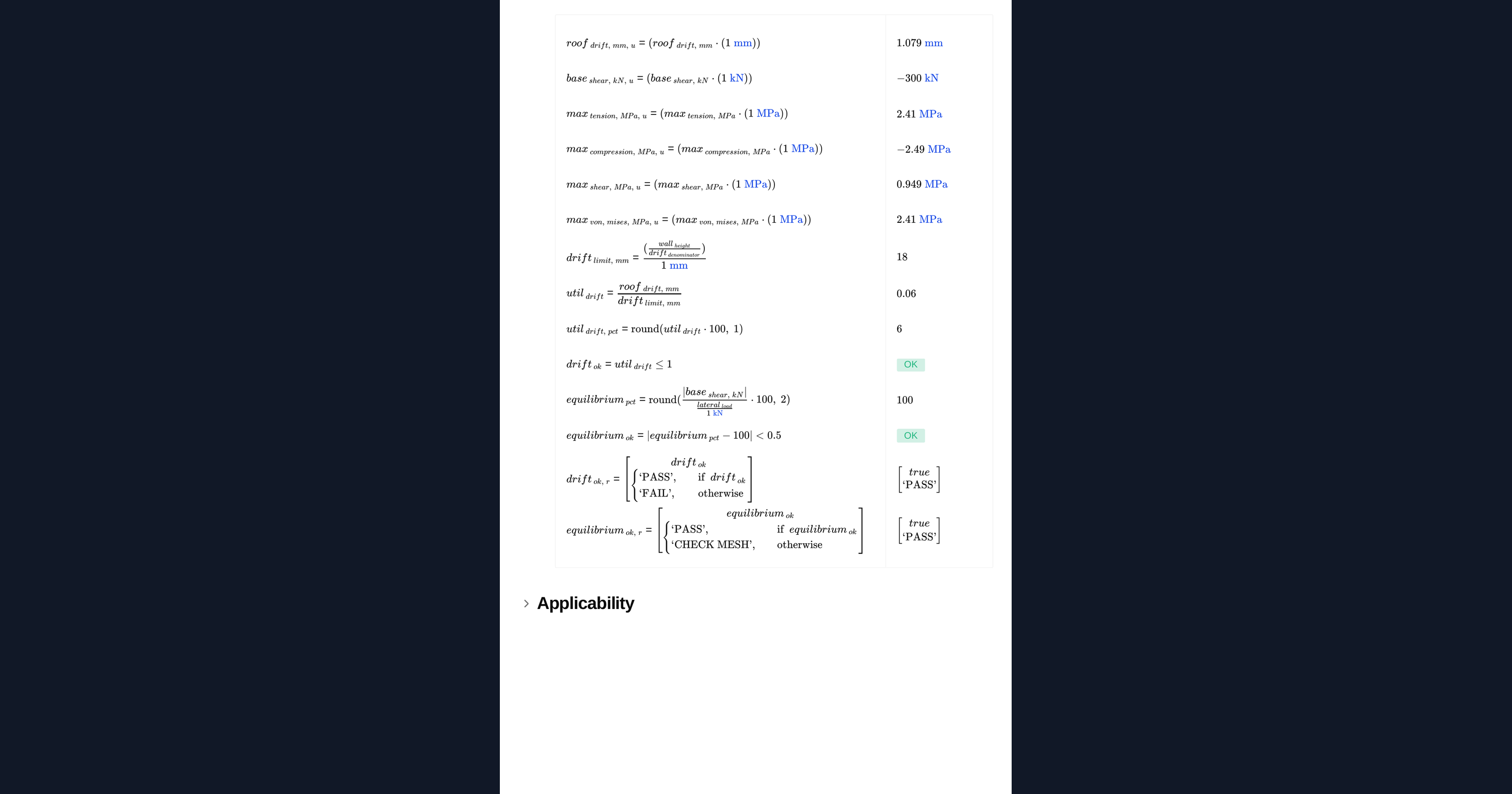
The equilibrium check in the Summary is not decoration. Removing elements to form the openings can leave nodes attached to nothing, and a singular system of that kind still returns a successful solve from the linear solver while producing meaningless displacements. If the base shear does not come back equal to the applied load, the mesh is wrong and nothing else on the page should be believed.
What the analysis assumes
The material is linear elastic, isotropic and uncracked, with no reinforcement. Concrete cracks once the tensile stress reaches its tensile strength, and the opening corners will reach it long before the rest of the wall. That is not a failure. It is a design requirement: use the stress field to understand the load path, then size the trimming reinforcement around each opening to the governing code.
Corner stresses are also partly a mesh artefact. A re-entrant corner in an elastic continuum is a stress singularity, so the peak value there keeps climbing as the mesh refines and should be read as a location to detail, not an absolute number to design to.
Engineering templates
Common calculators
Design guides




Why not just idealise the wall as a coupled-wall frame?
A frame idealisation is a fair shortcut when the piers and spandrels are slender and well separated. It gets shakier as openings grow, move off-centre, or sit at irregular spacing, because it assumes where the load path goes rather than solving for it. Meshing the real geometry in plane stress makes no such assumption, so it stays honest for arbitrary opening layouts.
What does the equilibrium check actually catch?
It catches a broken mesh. Deleting elements to form an opening can strand nodes with nothing to hold them, which makes the system singular. A linear solver can still report a successful solve on a singular system while returning meaningless displacements. The check compares the recovered base shear against the applied lateral load. If they do not match, disregard every other result on the page.
The stress at the opening corners looks very high. Is the wall failing?
No. Two things are happening. First, a re-entrant corner in an elastic continuum is a singularity, so the reported peak is partly a mesh artefact and grows as the mesh refines. Second, concrete reaches its tensile strength at those corners well before the rest of the wall, which is expected. Treat the corners as the place to detail trimming reinforcement, not as a pass or fail number.
Does it model cracking or reinforcement?
No. The analysis is linear elastic, isotropic and uncracked, with no reinforcement modelled. It gives you the elastic load path around the openings. You size the reinforcement to that load path using the governing code.
How are the openings entered?
As fractions of the wall dimensions rather than absolute coordinates. That way the openings scale with the wall, and you can change the overall geometry without re-entering every opening.
Why plane stress rather than plane strain?
A shear wall is thin relative to its height and length and is free to strain through its thickness, so plane stress is the correct idealisation. Plane strain would suit a long body restrained out of plane, which is not how a wall behaves.
Learn about the benefits of using CalcTree on engineering projects!