
Analyse a deep or transfer beam in 2D plane stress. Mesh it, run a real OpenSees FE analysis and read horizontal, vertical and von Mises stress contours.

This template is not available yet. You can sign up and create it yourself!
Or let us know if you'd like to be notified when it’s ready:
No items found.
No items found.
About the deep beam plane stress calculator
This calculation analyses a deep beam or transfer beam as a two-dimensional continuum rather than as a line element. It meshes the panel into quadrilateral finite elements, solves it in plane stress and draws the horizontal stress, the vertical stress and the von Mises stress as filled contours across the panel. The analysis runs a real finite element solve in the page using OpenSees, so it takes arbitrary geometry entered as a table rather than a single fixed standard case, and returns diagrams and contour plots alongside the numbers.
Why a deep beam is not an ordinary beam
Once a beam's span-to-depth ratio drops below roughly 2 to 3, plane sections no longer remain plane and ordinary bending theory stops describing the member. The internal force path becomes a strut and tie: load arches from the loaded face down to the supports in compression, and a horizontal tie carries the thrust across the bottom. Beam theory cannot show this, which is why a deep beam is either designed by a strut-and-tie model or analysed as a continuum. This page does the second.
How the analysis works
The panel is meshed into four-node quadrilateral elements in plane stress, each with two degrees of freedom per node, and solved by the direct stiffness method. Element stresses are averaged from their integration points to the nodes so the contours read smoothly rather than in blocks. The material is linear elastic and isotropic, so there is no cracking, no reinforcement and no redistribution.
What the contours tell you
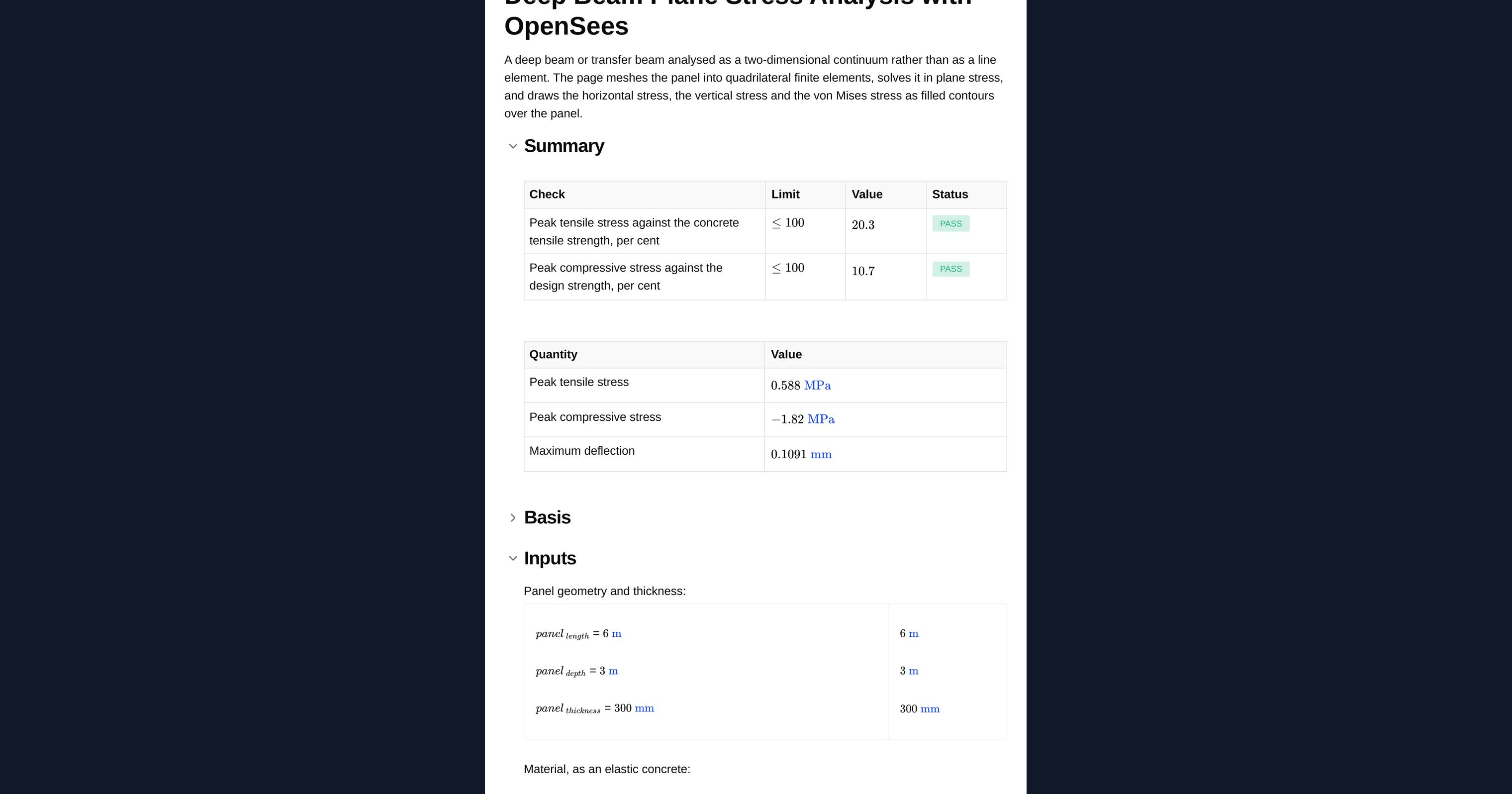
- Horizontal stress shows the tie directly. The band of tension along the bottom is the reinforcement requirement, and it stays roughly constant along the span rather than tapering to zero the way a shallow beam's does.
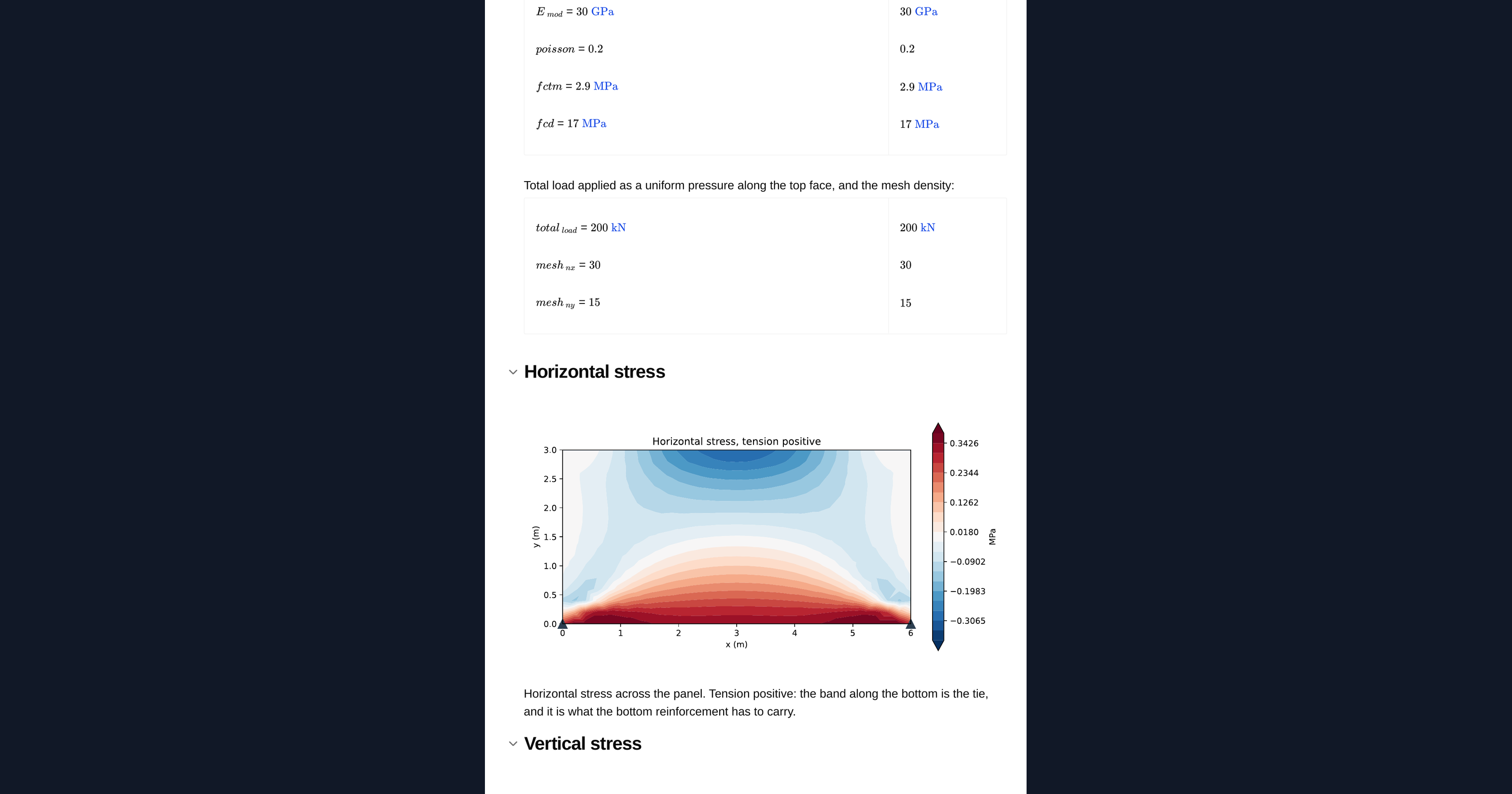
- Vertical stress shows how the load spreads from the loaded face and concentrates over the supports.
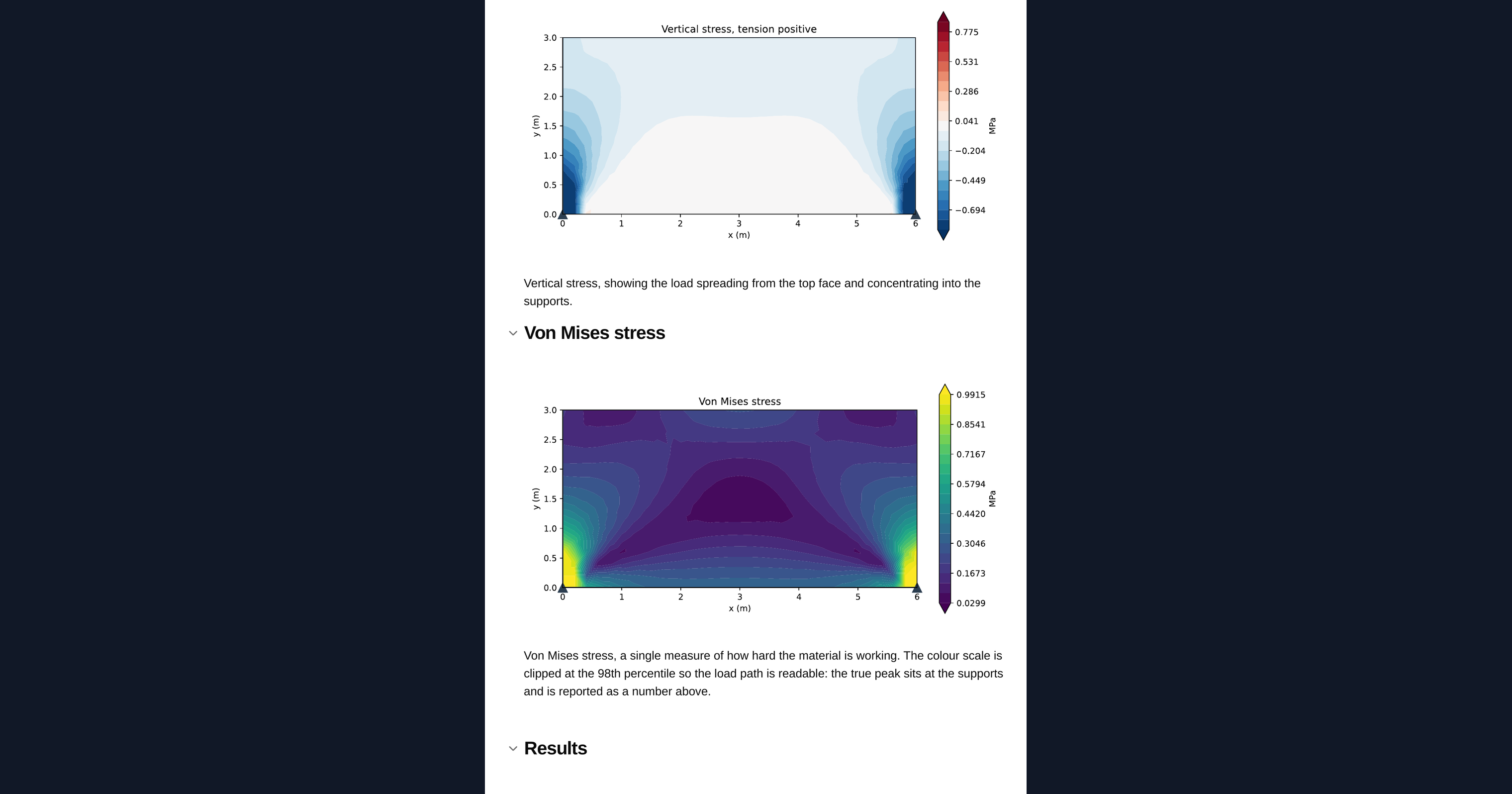
- von Mises stress is a single scalar for where the panel works hardest, useful for spotting concentrations at re-entrant corners and bearings.
Limits and caveats
The analysis is linear elastic and uncracked, which is its single biggest limitation. Concrete cracks as soon as the tensile stress reaches its tensile strength, and once it does the elastic stress field shown here is no longer the real one: tension migrates into the reinforcement and the compression field steepens. The tension result is therefore a cracking indicator, not a strength check. Exceeding it means the panel cracks and needs reinforcement designed for the tie force, not that it fails.
Use the contours to understand and size the load path, then design the reinforcement with a strut-and-tie model to the governing code. The tie force is the integral of the tensile stress block along the bottom, not the peak value. Stress concentrations at the supports are a mesh artefact as much as a real effect: a point support in a continuum model gives a stress that rises without limit as the mesh is refined, so read the field a short distance away from the bearing rather than the single peak node.
Engineering templates
Common calculators
Design guides




Frequently asked questions
When should I treat a beam as a deep beam?
When the span-to-depth ratio drops below about 2 to 3. Below that, plane sections no longer remain plane, ordinary bending theory no longer describes the member, and the force path becomes a strut and tie. Transfer beams and pile caps often fall in this range.
What is plane stress and why is it used here?
Plane stress models a thin panel loaded in its own plane, with no stress through the thickness. It suits a deep beam or wall panel where the depth and span are large relative to the thickness, and it reduces the problem to a two-dimensional continuum that solves quickly.
Does this calculation design the reinforcement?
No. It shows you the elastic load path and the tension field so you can see where the tie sits and how the load spreads. You still design the reinforcement with a strut-and-tie model to the governing code. The tie force is the integral of the tensile stress block along the bottom, not the peak stress value.
Why does the analysis ignore cracking?
The material is linear elastic, isotropic and uncracked, which keeps the solve fast and transparent. Real concrete cracks once the tensile stress reaches its tensile strength, after which the elastic field is no longer accurate. Treat the tension result as a cracking indicator rather than a strength check.
Why are the stresses so high at the supports?
A point support in a continuum model produces a stress concentration that grows without limit as the mesh is refined, so a large part of that peak is a mesh artefact. Read the stress field a short distance away from the bearing, or model a realistic bearing width, rather than trusting the single peak node.
What does the von Mises contour add?
It collapses the stress state into one scalar that flags where the panel works hardest. It is useful for spotting concentrations at re-entrant corners, openings and bearings that the individual horizontal and vertical plots might not make obvious at a glance.
Learn about the benefits of using CalcTree on engineering projects!