Design isolated concrete spread footings per ACI 318-19. Check bearing, flexure, shear, and punching with load combos and eccentricity. Free CalcTree template.

This template is not available yet. You can sign up and create it yourself!
Or let us know if you'd like to be notified when it’s ready:


No items found.
No items found.
About this Concrete Pad Footing Calculator
This Concrete Pad Footing Calculator streamlines the foundation design process according to the ACI 360R-10 guidelines. It calculates the minimum slab thickness, reinforcement details, and crack width based on underlying ground conditions and soil characteristics. It evaluates flexural, bearing, and shear stresses to establish the minimum slab thickness, required reinforcement, and estimated crack width. Additionally, it verifies the bearing stress on dowels at construction joints in compliance with the ACI 360R-10 guidelines.
This calculator is ideal for:
- Structural Engineers: Size an isolated footing, set reinforcement in both directions, and verify bearing, flexure, shear, and punching in one pass.
- Civil Contractors: Accurately estimate materials and optimize construction methods for slab on grade construction.
- Geotechnical engineer: Provide allowable soil bearing and surcharge inputs so the structural design aligns with ground parameters and settlement limits.
Efficiently design pad footings with this calculator: transparent formulas, unit-aware inputs/outputs, and pass/fail checks that follow ACI 318-19. It’s delivered as a reusable template you can duplicate and adapt across projects.
More info on Concrete Pad Footing Calculator (ACI 318-19)
Inputs and Parameters
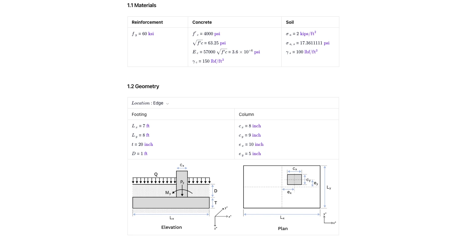
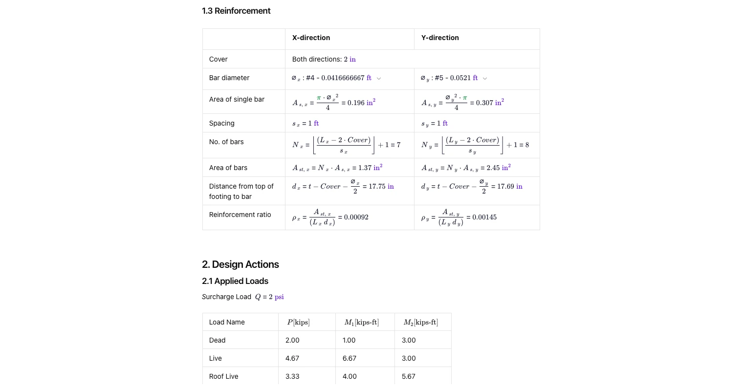
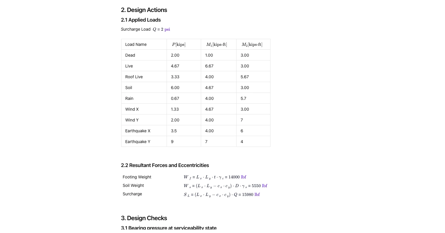
Define materials (concrete, reinforcement, soil), footing geometry (plan sizes, thickness, depth/overburden), and column offsets/eccentricities. Reinforcement cover, bar sizes, spacing, and reinforcement ratio are set separately for each direction. A surcharge pressure and a full set of vertical load and biaxial moment actions are provided.
Geometry & Layout
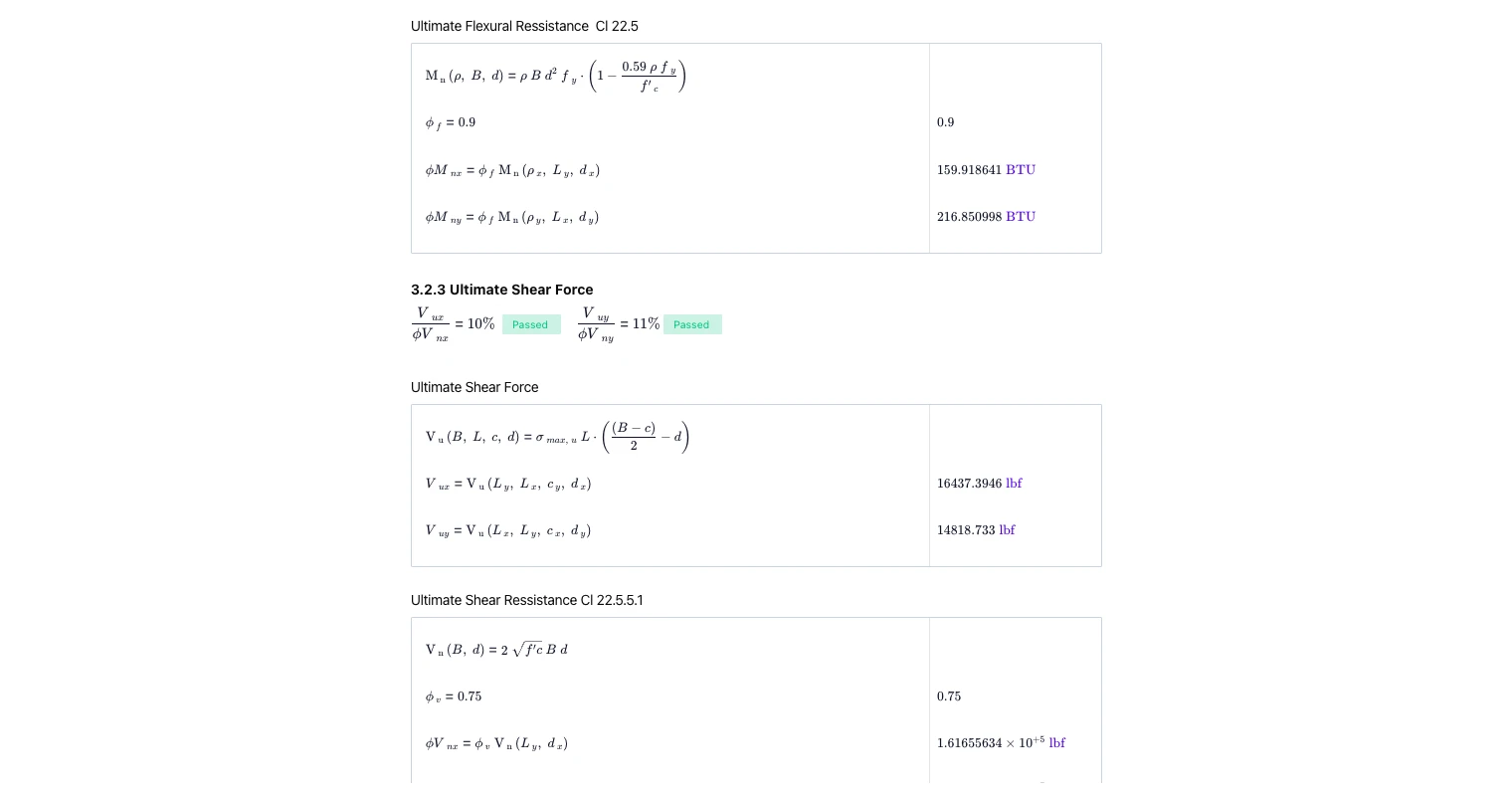
The template supports interior/edge conditions and shows elevation and plan sketches with the column location, eccentricities, and critical sections for bending and shear. Reinforcement is specified in orthogonal directions with bar count and spacing derived from plan dimensions and cover.
Design Actions & Combinations
Service and ultimate combinations are assembled from the applied loads (dead, live, roof live, soil, environmental actions) into serviceability and strength load sets. Resultant footing weight, soil weight, surcharge, and eccentricities are calculated and carried into checks. Combination tables make it easy to identify the governing case.
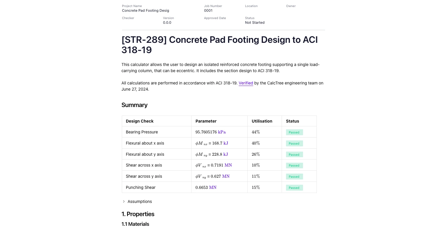
Design Checks Per ACI 318-19
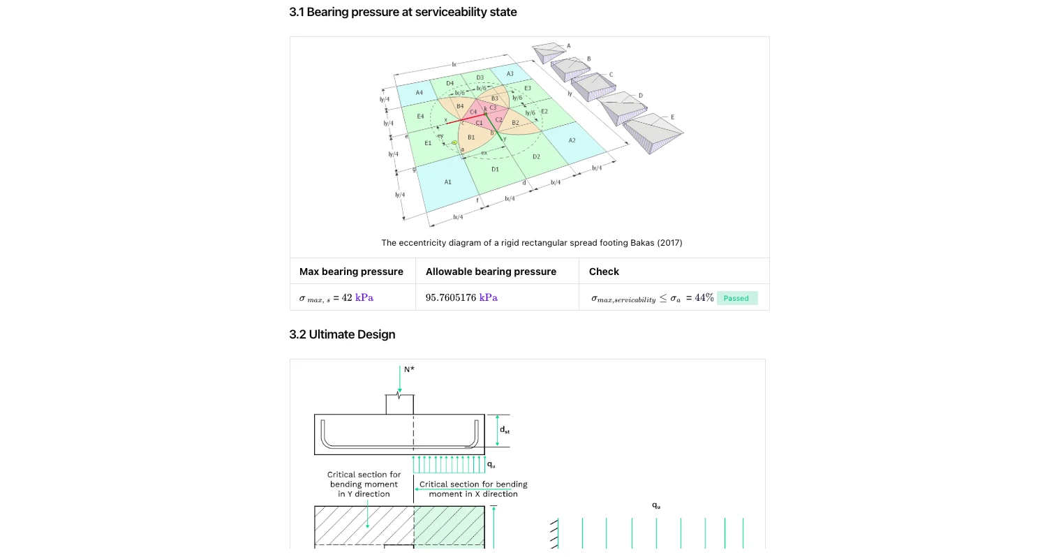
- Service bearing pressure: computes pressure distribution under eccentric loading and verifies maximum bearing against the allowable. The eccentricity region is visualised to confirm contact conditions.
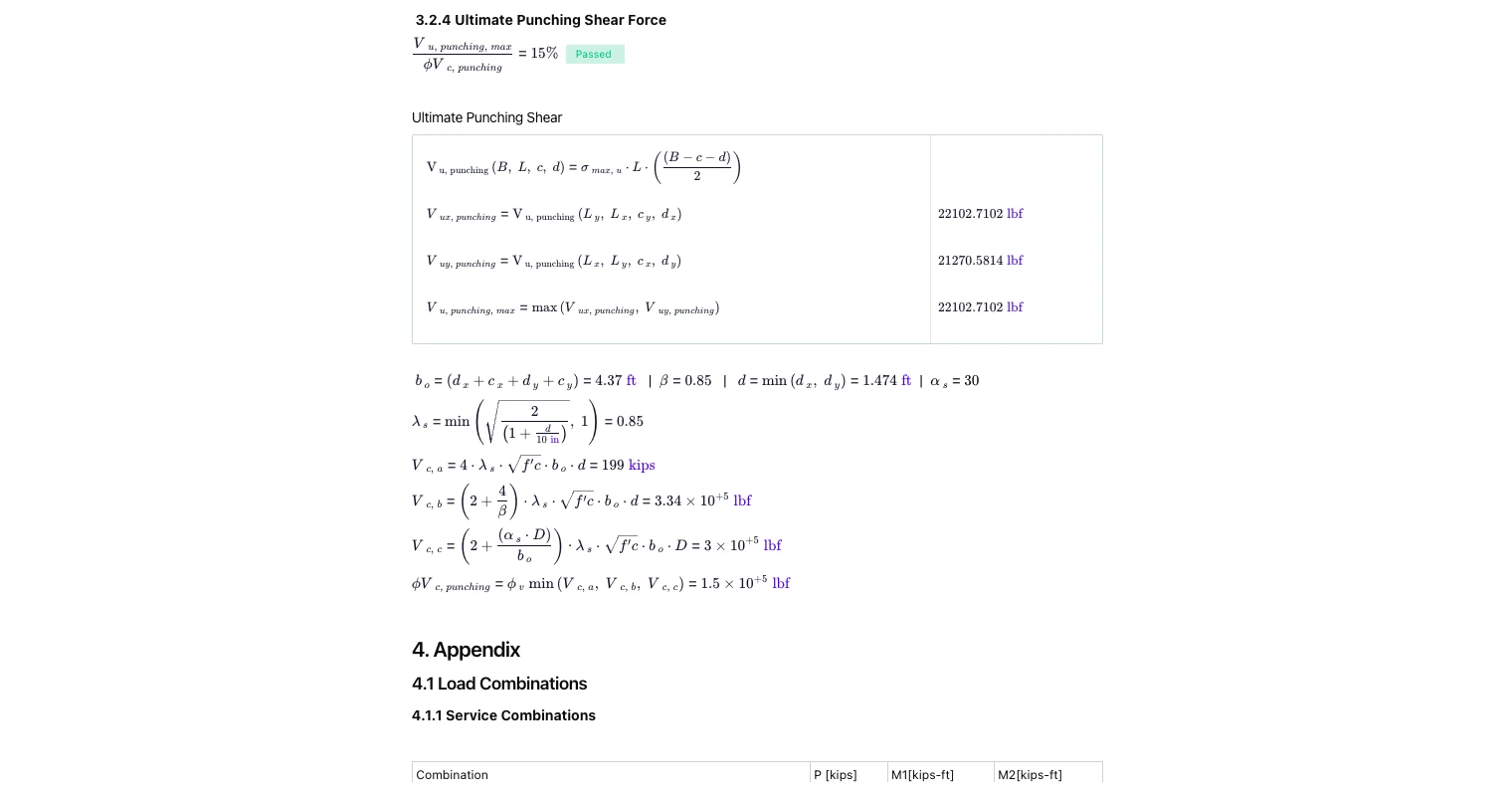
- Ultimate flexural strength (two directions): determines demand at critical sections and compares to nominal strength with strength reduction factors.
- Ultimate one-way shear (two directions): evaluates shear demand along critical sections parallel to each axis and checks against concrete shear resistance with φ-factors.
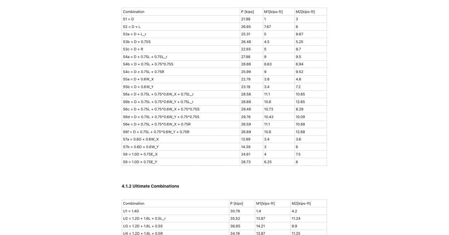
- Ultimate punching shear: builds the control perimeter around the column, applies reduction factors and β limits, and compares punching demand to concrete capacity.
All checks report utilisation and pass/fail, with equations shown for traceability.
Common Calculation Errors to Avoid
- Treating a pad as concentric when the column is offset: ignoring eccentricity can under-predict service bearing pressure and over-estimate capacity in the concrete pad footing calculator.
- Using ultimate combinations for service bearing: serviceability bearing must be checked with service load cases; keep ACI 318-19 strength checks separate.
- Forgetting surcharge and overburden: exclude or mis-specify surcharge and soil depth and the spread footing bearing verification becomes non-conservative.
- Placing bending sections at the column face only: ACI 318-19 requires critical sections defined relative to the column and reinforcement depth; use the provided critical lines in both directions.
- Mixing units: the template is unit-aware; ensure soil, geometry, and steel inputs use consistent units before running footing design checks.
- Under-estimating punching perimeter: do not hand-shorten the control perimeter at edges without applying the correct β and edge conditions per code.
Engineering templates
Common calculators
Design guides
FAQs
What checks does this ACI 318-19 footing calculator perform?
It verifies service bearing pressure, ultimate flexural strength in both orthogonal directions, ultimate one-way shear in both directions, and ultimate punching shear, all with strength-reduction factors and governing load combinations.
How are eccentric loads handled?
Column offsets and biaxial moments produce eccentricity. The tool computes the contact stress distribution and shows the governing region so you can confirm partial contact vs full contact before proceeding to ultimate checks.
Where are the critical sections taken?
Critical sections for bending and shear are positioned per ACI 318-19 rules relative to the column face and effective depth. The punching shear control perimeter is generated around the column with appropriate reductions near edges/corners.
Can I customise bar size, spacing, and cover?
Yes. Bar size and spacing are independent per direction, with cover set once. The tool calculates bar count, reinforcement areas, and resulting reinforcement ratio automatically.
Does this replace a geotechnical check?
No. You still need allowable soil bearing and settlement guidance from geotechnical inputs. This calculator consumes those values to keep the structural design consistent with ground performance.
Can I reuse this on other projects?
Absolutely— add this template and save your firm’s defaults. You can also link it into a broader footing/column workflow or a report pipeline using other CalcTree templates.


Learn about the benefits of using CalcTree on engineering projects!