Free Concrete Column Design Tool to ACI-318-19. Step-by-step, engineering-grade tool with downloadable report.

This template is not available yet. You can sign up and create it yourself!
Or let us know if you'd like to be notified when it’s ready:
No items found.
No items found.
About this Concrete Column Design to ACI-318-19 Tool
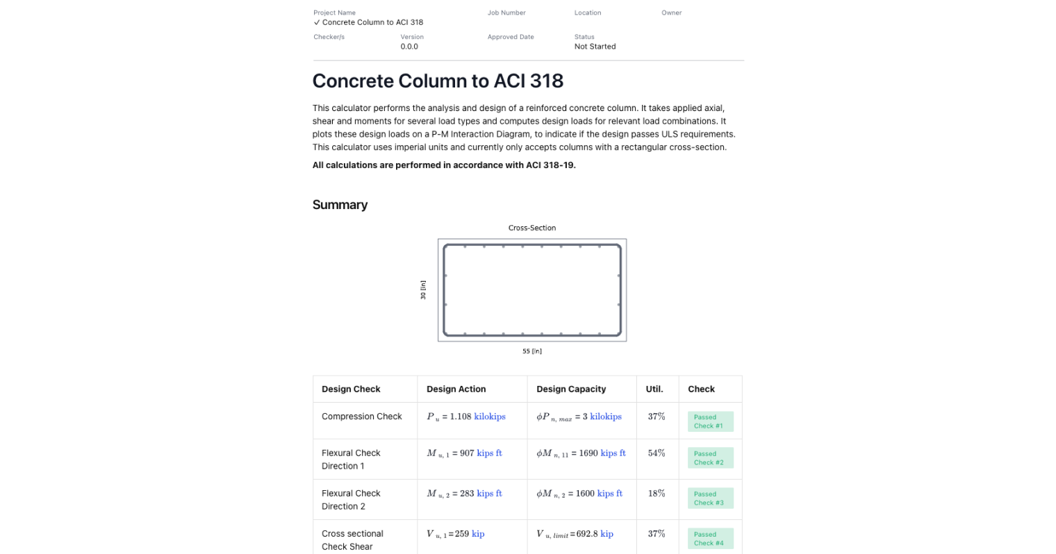
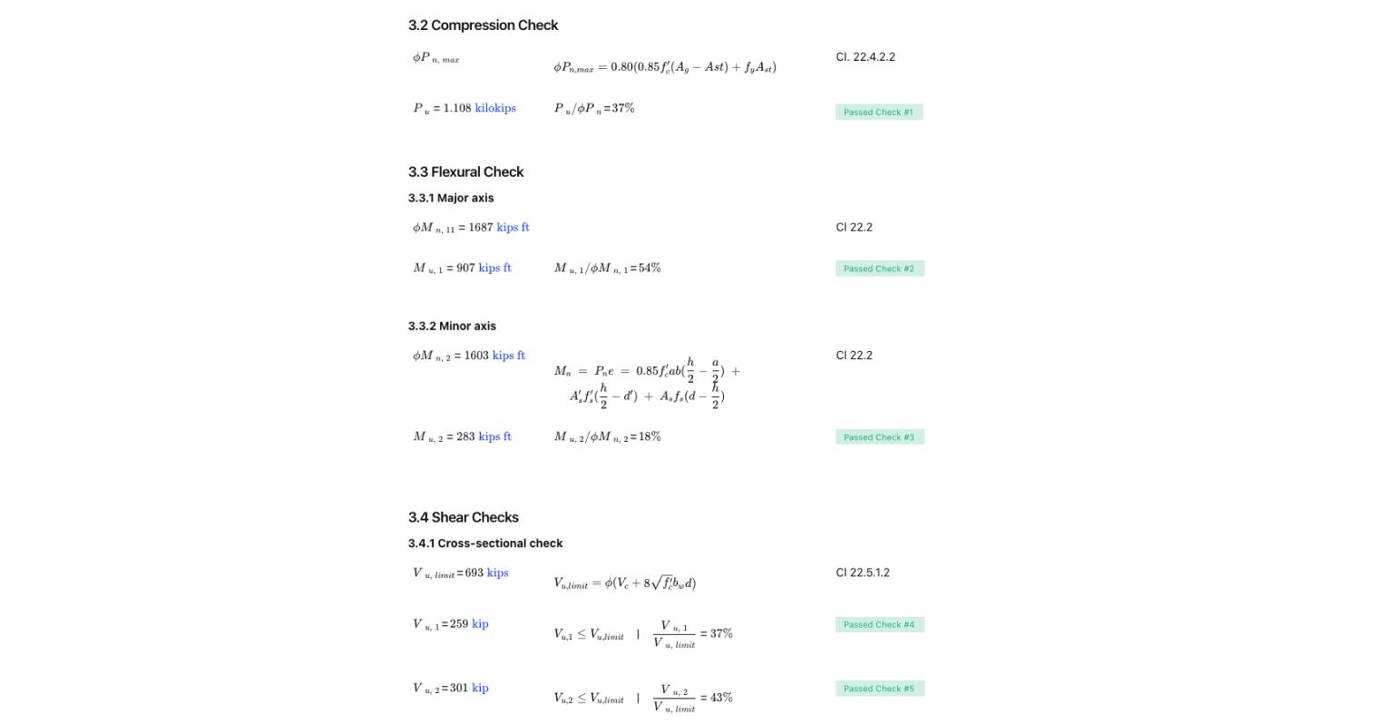
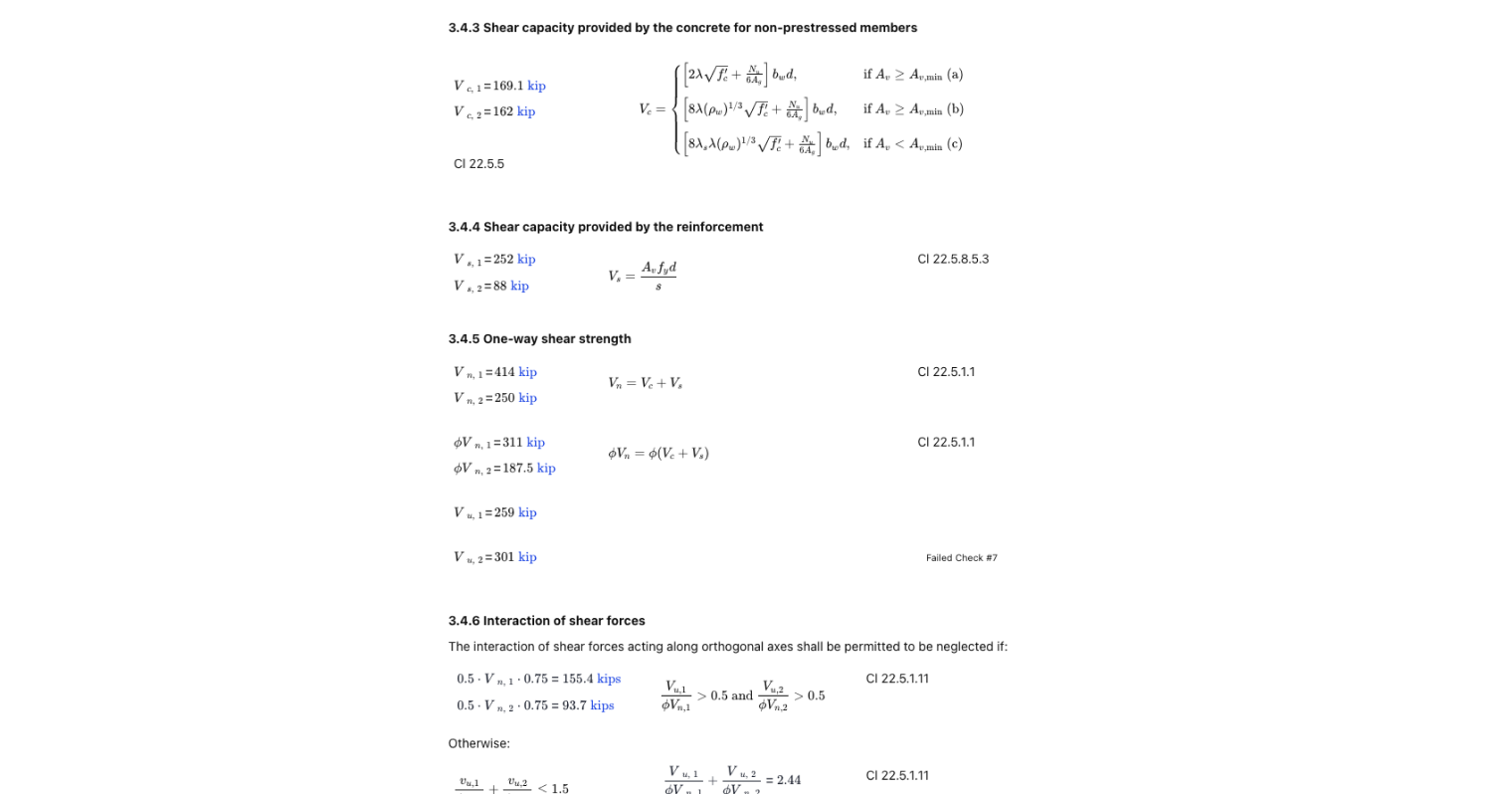
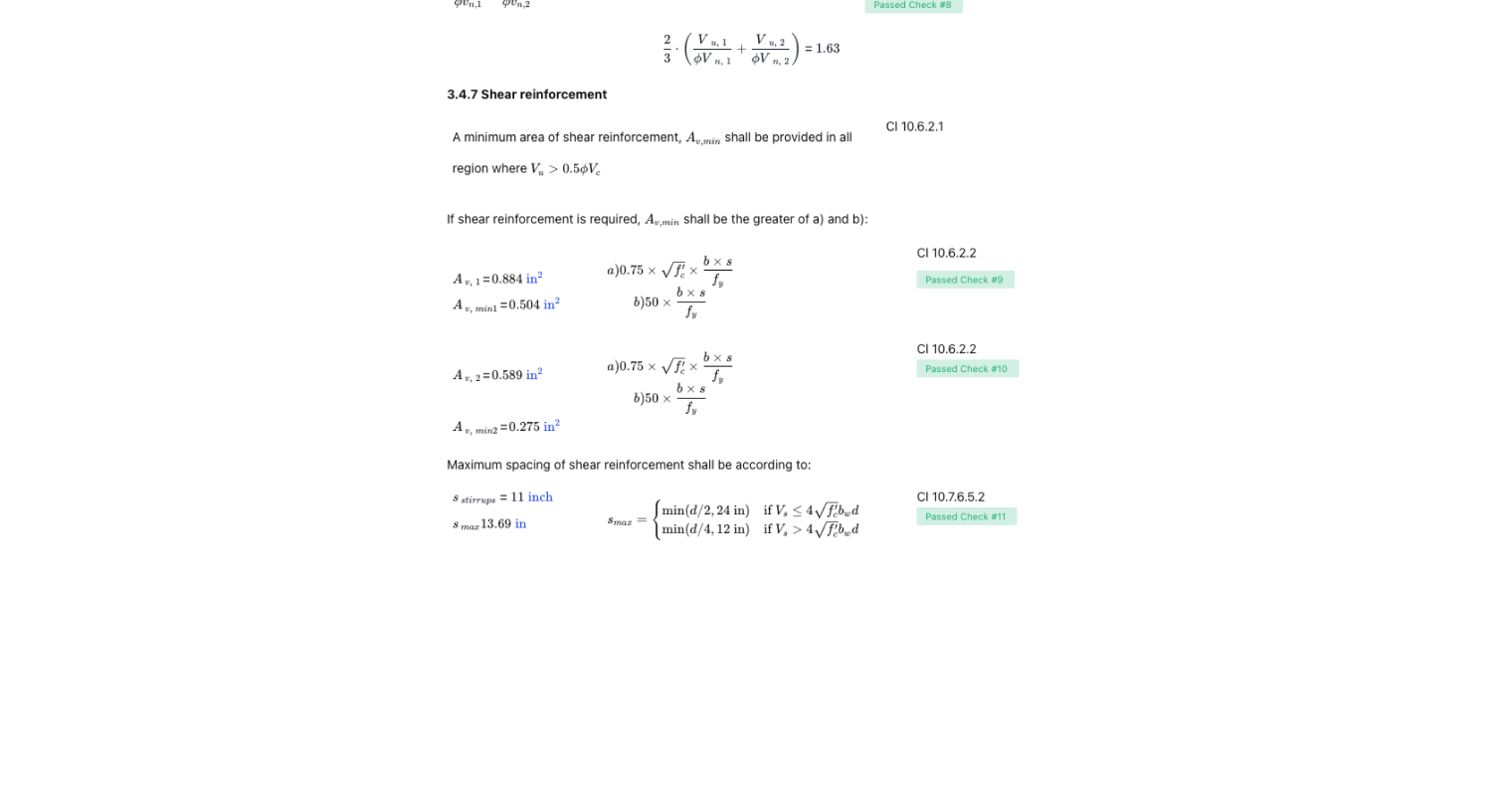
The Concrete Column Design to ACI-318-19 tool provides an efficient method for analyzing and designing rectangular reinforced concrete columns. It considers the applied axial, shear, and moment loads, producing load combinations and plotting the results on a P-M Interaction Diagram. This diagram helps users determine if the design satisfies the Ultimate Limit State (ULS) requirements, with all calculations based on ACI 318-19 standards.
This tool is for:
- Structural engineers who need to ensure the safety and compliance of concrete column designs in accordance with the latest ACI standards.
- Consultants and designers working on complex reinforced concrete structures, needing to verify load combinations and column strength under various conditions.
- Civil engineering students and educators learning about reinforced concrete column behavior, including the interaction of axial and moment loads.
Use this template to simplify the process of verifying column dimensions, steel reinforcement, and the interaction of axial and moment forces—all based on the latest ACI code.
General Info on Concrete Column Design to ACI-318-19
Understanding the Interaction Diagram
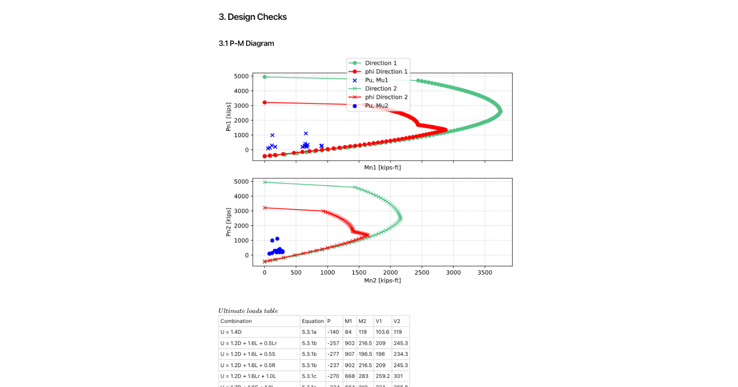
Every concrete column must be checked with an interaction diagram to understand the balance between axial compression, bending moment, and pure tension. These diagrams plot the nominal moment capacity against axial force and show how the column behaves between pure axial compression and pure tension. A column interaction diagram helps you verify whether your design loads sit inside the safe zone.
Reinforcement Ratio and Placement
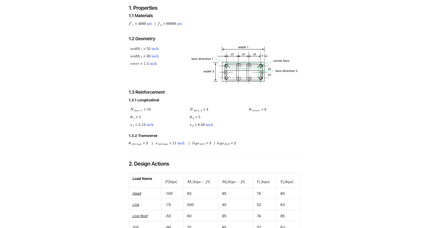
The reinforcement ratio defines how much steel reinforcement is in the cross sectional area of the column. Too low, and you risk brittle failure; too high, and the neutral axis moves unfavorably, reducing ductility. Correct rebar placement with appropriate longitudinal reinforcement and transverse reinforcement is crucial for both rectangular and circular columns.
Strength Reduction Factors and Material Properties
The ACI code requires using a strength reduction factor (ϕ) to account for uncertainty in material properties and construction practices. The factor varies depending on whether the column is controlled by pure axial compression, bending capacity, or pure tension conditions. It’s also affected by the column’s balanced point—the transition from tension- to compression-controlled behavior.
Stress Blocks and Strain Diagrams
A rectangular stress block is used in ACI-318-19 to model concrete compression strength. Paired with a strain diagram, it allows you to track how the column transitions from decompression point to full compression. This helps ensure your load calculation and moment capacity checks are consistent with code.
Common Calculation Errors to Avoid
When working on reinforced concrete column design, certain errors can compromise safety and efficiency:
- Ignoring Load Combinations: Using only dead load and live load separately instead of the correct load combinations can underestimate required strength.
- Misjudging Reinforcement Ratio: Placing too much or too little reinforcement can shift the neutral axis beyond code limits.
- Skipping Interaction Diagram Checks: Failing to validate against the interaction diagram risks exceeding the design bending moment or axial load capacity.
- Incorrect Strength Reduction Factor: Applying the wrong strength reduction factor means your column design could be unconservative.
- Overlooking Slender Columns: Long, slender columns require additional checks for stability, not just strength.
- Not Considering Seismic Loads or Fire Resistance: Missing these factors means your concrete structures may not perform under critical conditions.
Engineering templates
Common calculators
Design guides
FAQs
What is the purpose of an interaction diagram in concrete column design?
It visually shows the relationship between axial force and bending moment, helping verify that the design loads fall within safe limits.
How much reinforcement should I use in a column?
The reinforcement ratio must comply with ACI limits—generally between 1%–8% of the cross sectional area—to balance strength and ductility.
What’s the difference between longitudinal and transverse reinforcement?
Longitudinal reinforcement provides the main strength against axial compression and bending, while transverse reinforcement (ties or spirals) holds steel bars in place and prevents buckling.
Can I design reinforced concrete columns using only interaction diagrams?
No—you must also verify load combinations, material properties, and safety factors for a complete concrete column design.
Summary and References
Designing a concrete column to ACI-318-19 involves more than just plugging numbers into a formula. Use this template to make your job easier when also considering reinforcement ratio, interaction diagrams, strength reduction factors, and load calculation methods to ensure your reinforced concrete columns are safe and code-compliant.
For further guidance, refer to:
- ACI 318-19: Building Code Requirements for Structural Concrete


Learn about the benefits of using CalcTree on engineering projects!