
Track a moving point load across a simply supported span, build bending moment and shear envelopes, see influence lines, all from a real OpenSees analysis.

This template is not available yet. You can sign up and create it yourself!
Or let us know if you'd like to be notified when it’s ready:
No items found.
No items found.
About this online moving load and influence line calculator
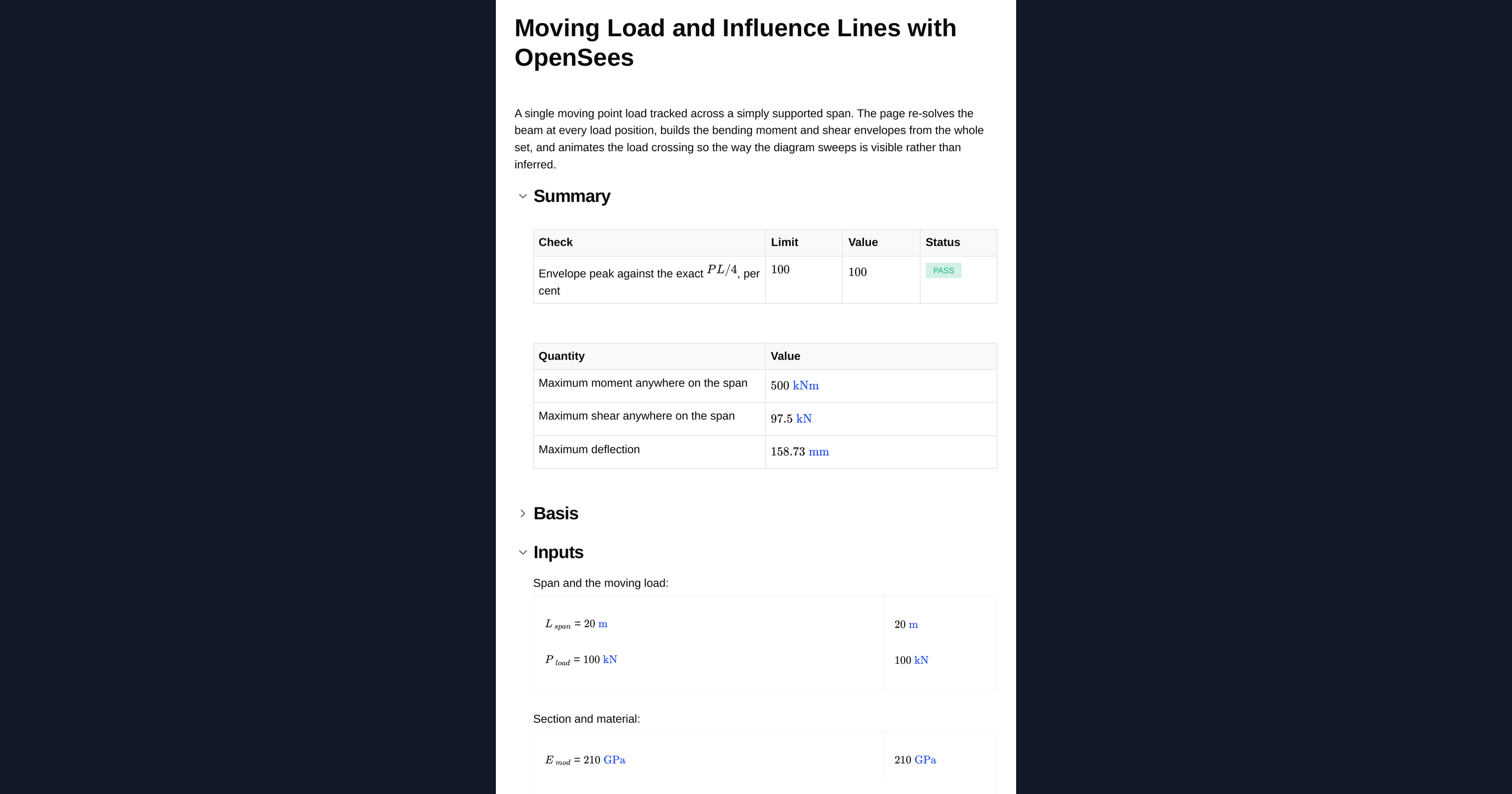
This calculation tracks a single moving point load as it crosses a simply supported span and shows you the two things a moving load actually produces: the influence lines that describe how a response at one section changes as the load moves, and the envelopes that describe the worst case a member has to be designed for. It runs a real finite element analysis in the page using OpenSees, so the span geometry is entered as a table rather than being locked to a single textbook case, and it returns bending moment and shear diagrams alongside the numbers.
Why a moving load is not a single analysis
A moving load is many analyses, not one. The bending moment at a given section depends on where the load happens to sit, and the value a member must carry is the worst that occurs anywhere during the crossing. Two ideas fall out of that, and they are easy to confuse:
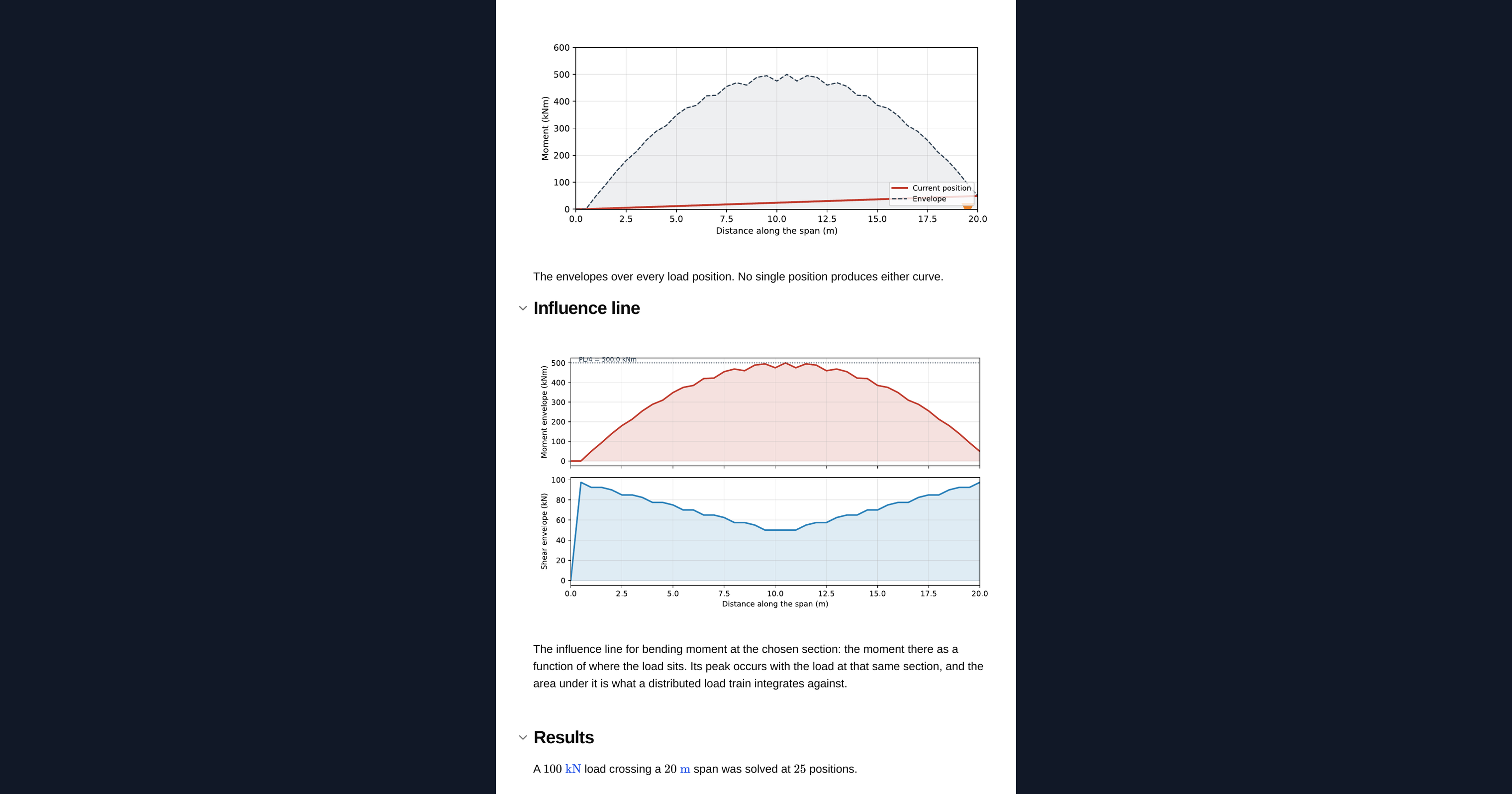
- An influence line fixes a section and varies the load position. It answers a question like "how does the moment at midspan change as the vehicle crosses?" It is the quantity you integrate against a load train.
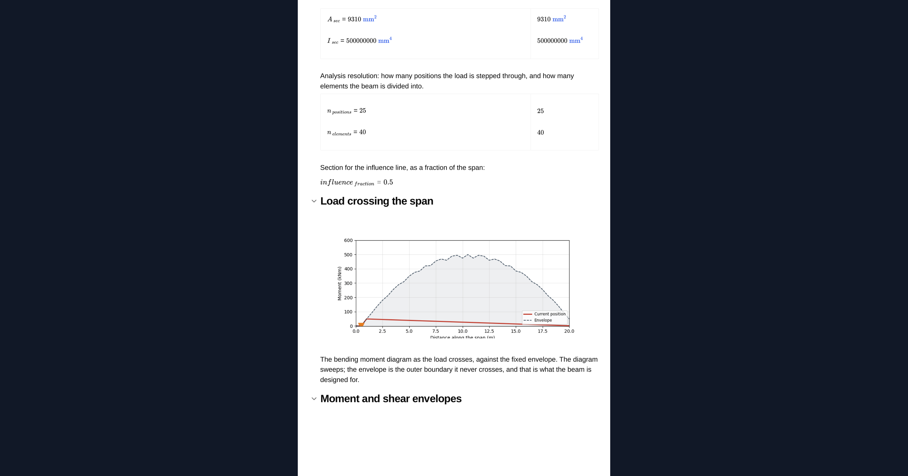
- An envelope fixes nothing. At every section it records the worst value seen over all load positions. It is the design diagram, and no single load position produces it.
How the calculation works
The page computes both by brute force. The beam is re-solved at every load position, and the envelopes are the point-by-point maximum and minimum taken over that whole set. This is slower than the classical Muller-Breslau construction, but it makes no assumptions and it extends to any support arrangement without new theory.
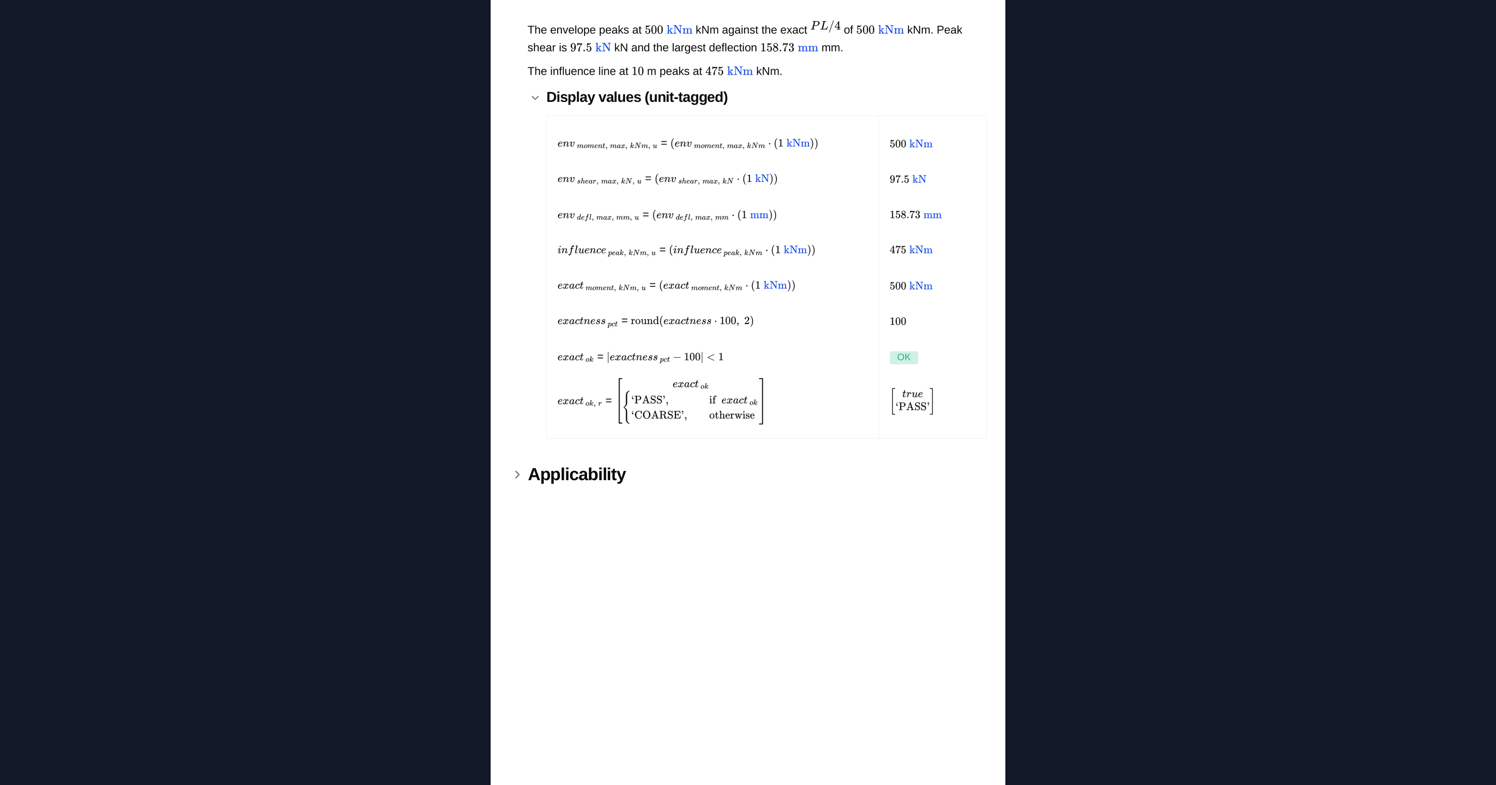
Because the exact answers are known for a single point load on a simple span, the page checks itself. The envelope peak moment must equal PL/4, reached when the load sits at midspan, and the peak shear must approach P as the load nears a support. Those values are computed independently and compared against the envelope, so the calculation verifies its own result rather than asking you to take it on trust.
Limits and caveats the page states
The envelope peak is only as accurate as the resolution. The load is stepped through a finite number of positions and applied at nodes, so if none of those positions lands where the true maximum occurs, the envelope will undershoot it. The self-check compares the envelope against the exact PL/4 precisely to expose this: if it reads below 100 per cent, raise the number of load positions or elements. That is a discretisation warning, not an error in the analysis.
This is a single point load. A real vehicle is a load train of several axles at fixed spacing, and its envelope is not the single-load envelope scaled up. The axles interact, and the critical position is found by placing the whole train rather than one wheel. You can extend the model by applying several loads at fixed offsets and stepping the train across the span.
The analysis is first-order linear elastic on a simply supported prismatic span. Within those bounds it gives you exact influence lines, verified envelopes, and an animation of the load crossing so the way the diagram sweeps is something you can watch rather than something you have to infer.
Engineering templates
Common calculators
Design guides




Frequently asked questions
What is the difference between an influence line and an envelope?
An influence line fixes one section and varies the load position, telling you how a single response changes as the load crosses. An envelope fixes nothing: at every section it records the worst value over all load positions. The influence line is what you integrate against a load train; the envelope is the design diagram.
What is the maximum bending moment from a single moving point load?
On a simply supported span the peak bending moment is PL/4, produced when the load sits at midspan. The peak shear approaches P as the load nears a support. This calculation computes both from the envelope and checks them against those exact values.
Why does the self-check read below 100 per cent?
The load is stepped through a finite number of positions and applied at nodes. If none of those positions lands exactly where the true maximum occurs, the envelope undershoots the exact PL/4 and the check reads under 100 per cent. Raise the number of load positions or elements to close the gap. It is a resolution warning, not an analysis error.
Can I model a multi-axle vehicle or load train?
Not directly with this single-load version. A load train's envelope is not the single-load envelope scaled up, because the axles interact and the critical position is found by placing the whole train. You can extend the model by applying several loads at fixed offsets and stepping the train across the span.
What analysis actually runs behind the page?
A real OpenSees finite element analysis runs in the page. The span geometry is entered as a table, the beam is re-solved at every load position, and the envelopes are built from that whole set. You get diagrams and contour plots alongside the numbers.
What are the assumptions and limits?
The analysis is first-order linear elastic on a simply supported prismatic span with a single moving point load. It does not cover material or geometric non-linearity, continuous or fixed supports beyond what the table describes, or dynamic amplification.
Learn about the benefits of using CalcTree on engineering projects!