Elastic and plastic section modulus formulas for rectangles, I sections, circles, tubes, RHS and T sections, with a worked example to AS 4100 and Eurocode 3.
The section modulus formula, \( Z = I / y \), turns a moment of inertia into the one number a bending check needs: divide the applied moment by \( Z \) and you have the extreme fibre stress. Because it folds together both how much material a section has and how far that material sits from the neutral axis, it is the property that section tables, steel codes and timber codes all key on for bending capacity.
This page gives the elastic and plastic section modulus formulas for the common shapes, explains when a section has two values, and works through a 300 mm I section to the point of a code moment capacity under AS 4100 and Eurocode 3. The moments of inertia it starts from are covered in our moment of inertia guide.
What the section modulus is
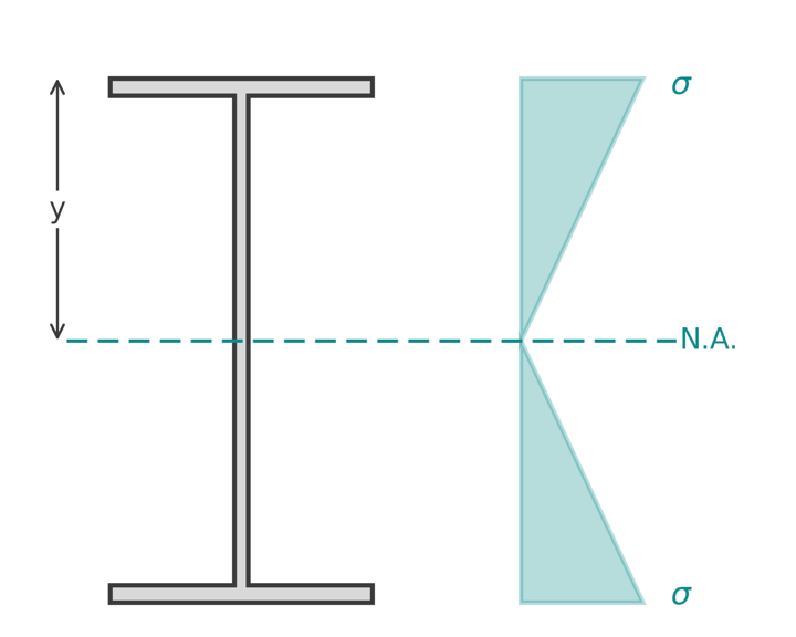
Elastic bending theory gives the stress at a distance \( y \) from the neutral axis as \( \sigma = M y / I \). The largest stress is at the fibre furthest from the axis, \( y_{max} \), so:
$$ \sigma_{max} = \frac{M}{I / y_{max}} = \frac{M}{Z} $$
$$ Z = \frac{I}{y_{max}} $$
where
\( I \) is the second moment of area about the bending axis
\( y_{max} \) is the distance from the neutral axis to the extreme fibre
\( Z \) is the elastic section modulus (written \( W_{el} \) in Eurocode 3, and \( S \) in American practice, which is the reverse of the Australian convention)
Units are length cubed: \( \text{mm}^3 \), usually reported as \( 10^3 \text{ mm}^3 \). Section tables often use \( \text{cm}^3 \), and \( 1 \text{ cm}^3 = 10^3 \text{ mm}^3 \).
Setting \( \sigma_{max} = f_y \) gives the moment at first yield, \( M_y = f_y Z \). That is the capacity of a section that cannot be allowed to yield through its depth, which in steel design means a slender or non-compact section.
Elastic versus plastic section modulus
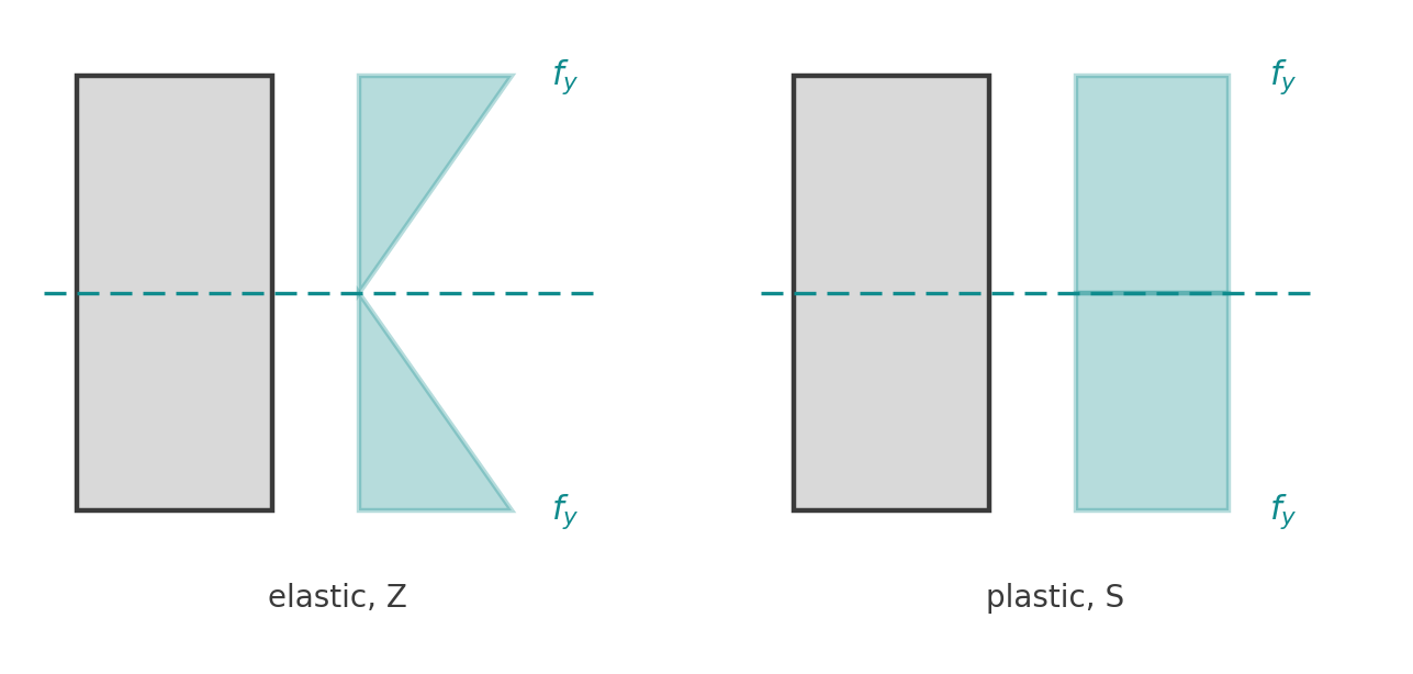
If the section is stocky enough to yield right through without local buckling, the stress block becomes two rectangles at \( f_y \), one in compression and one in tension, split at the equal-area axis. The moment this block resists is \( M_p = f_y S \), where \( S \) is the plastic section modulus:
$$ S = A_c \, \bar{y}_c + A_t \, \bar{y}_t $$
\( A_c \) and \( A_t \) are the areas above and below the equal-area axis, and \( \bar{y}_c \), \( \bar{y}_t \) are the distances from that axis to their centroids. For a symmetric section this simplifies to \( S = A \bar{y}_{half} \) where \( \bar{y}_{half} \) is the half-section centroid distance. The ratio \( S / Z \) is the shape factor: 1.5 for a rectangle, about 1.10 to 1.18 for rolled I sections, and 1.70 for a solid circle.
Section modulus formulas for common shapes
The section properties of common shapes calculator computes \( Z \) about both axes for the rectangle, I or H section, CHS and RHS from their dimensions.
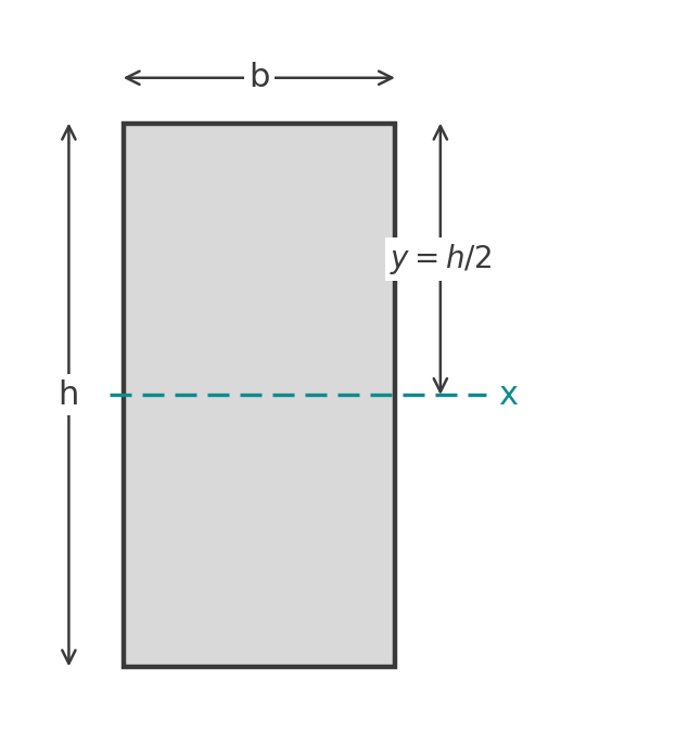
All formulas are about the horizontal centroidal axis unless stated.
Rectangle, b wide and h deep
$$ Z = \frac{b h^2}{6}, \qquad S = \frac{b h^2}{4} $$
About the vertical axis, swap \( b \) and \( h \). For a 200 mm by 400 mm timber or concrete section, \( Z = 200 \times 400^2 / 6 = 5.33 \times 10^6 \text{ mm}^3 \) and \( S = 8.00 \times 10^6 \text{ mm}^3 \).
Symmetrical I or H section
$$ Z_x = \frac{b d^3 - (b - t_w)(d - 2 t_f)^3}{6 d} $$
$$ S_x = b \, t_f \, (d - t_f) + \frac{t_w (d - 2 t_f)^2}{4} $$
The \( S_x \) formula is the two flange couples plus the web couple. The weak axis values are \( Z_y = I_y / (b/2) \) and \( S_y = t_f b^2 / 2 + (d - 2t_f) t_w^2 / 4 \).
Solid circle, diameter d
$$ Z = \frac{\pi d^3}{32}, \qquad S = \frac{d^3}{6} $$
A 50 mm bar has \( Z = \pi \times 50^3 / 32 = 12.3 \times 10^3 \text{ mm}^3 \).
Circular hollow section, outer D and inner d
$$ Z = \frac{\pi \left( D^4 - d^4 \right)}{32 D}, \qquad S = \frac{D^3 - d^3}{6} $$
A 168.3 mm by 4.8 mm CHS has \( d = 158.7 \) mm and \( Z = 98.0 \times 10^3 \text{ mm}^3 \).
Rectangular hollow section, B wide, H deep, thickness t
Ignoring corner radii, with \( b = B - 2t \) and \( h = H - 2t \):
$$ Z_x = \frac{B H^3 - b h^3}{6 H}, \qquad S_x = \frac{B H^2 - b h^2}{4} $$
For a 150 mm by 100 mm by 6 mm RHS bending about its strong axis, \( I_x = (100 \times 150^3 - 88 \times 138^3)/12 = 8.85 \times 10^6 \text{ mm}^4 \) and \( Z_x = 8.85 \times 10^6 / 75 = 118 \times 10^3 \text{ mm}^3 \). Real rolled sections have rounded corners that reduce this slightly, which is why tabulated values are a little lower.
Channel
About the strong axis a channel is symmetric, so the I section formula for \( Z_x \) applies unchanged: the two voids beside an I web and the single void beside a channel web both total \( b - t_w \) in width. Or more simply, \( Z_x = I_x / (d/2) \). About the weak axis the centroid is off-centre and there are two values, as for the T section below.
Sections with two section moduli
For a T or unsymmetric I, the composite section properties calculator finds the centroid first and reports both section moduli.
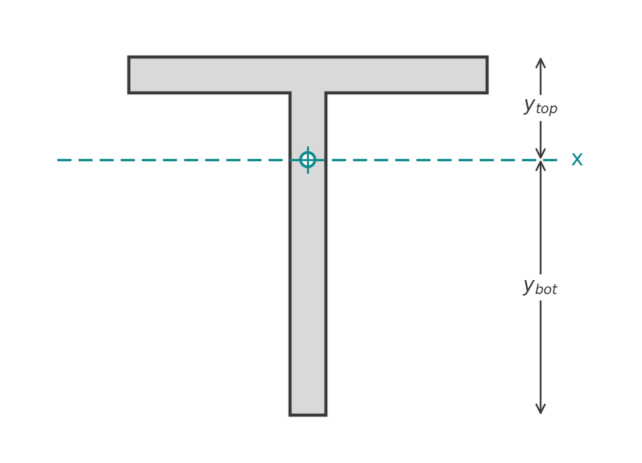
When the centroid is not at mid-depth, the top and bottom fibres are at different distances and each gets its own section modulus:
$$ Z_{top} = \frac{I}{y_{top}}, \qquad Z_{bot} = \frac{I}{y_{bot}} $$
The smaller value governs the elastic stress check, because that fibre reaches yield first. Which one is smaller depends on which way the centroid is pulled, and for a T section it is always the web tip.
T section
Take the T from our centroid formulas page: a 200 mm by 20 mm flange on a 180 mm by 20 mm web, centroid 142.6 mm above the web tip and 57.4 mm below the flange top. The moment of inertia about the centroid, by the parallel axis theorem, is:
- Flange: \( 200 \times 20^3 / 12 + 4000 \times (190 - 142.6)^2 = 133\,333 + 8\,975\,700 \)
- Web: \( 20 \times 180^3 / 12 + 3600 \times (142.6 - 90)^2 = 9\,720\,000 + 9\,971\,700 \)
- \( I = 28.8 \times 10^6 \text{ mm}^4 \)
$$ Z_{top} = \frac{28.8 \times 10^6}{57.4} = 502 \times 10^3 \text{ mm}^3, \qquad Z_{bot} = \frac{28.8 \times 10^6}{142.6} = 202 \times 10^3 \text{ mm}^3 $$
The web tip governs with less than half the flange value. Under sagging moment the web tip is in tension; under hogging it is in compression, which also raises a local buckling question for a slender web outstand.
Unsymmetrical I section
Same procedure: find the centroid, find \( I \), divide by each extreme fibre distance. The 300 mm deep section with a 200 mm top flange and 120 mm bottom flange on our I beam moment of inertia page has \( Z_{top} = 712 \times 10^3 \text{ mm}^3 \) and \( Z_{bot} = 524 \times 10^3 \text{ mm}^3 \).
Worked example: from section modulus to moment capacity
A welded I section has \( d = 300 \) mm, \( b = 150 \) mm, \( t_f = 10 \) mm and \( t_w = 8 \) mm, with \( f_y = 300 \) MPa. From the I section page, \( I_x = 77.7 \times 10^6 \text{ mm}^4 \).
Elastic section modulus:
$$ Z_x = \frac{77.73 \times 10^6}{150} = 518 \times 10^3 \text{ mm}^3 $$
Plastic section modulus:
$$ S_x = 150 \times 10 \times 290 + \frac{8 \times 280^2}{4} = 435\,000 + 156\,800 = 592 \times 10^3 \text{ mm}^3 $$
Shape factor \( S_x / Z_x = 1.14 \). First-yield moment \( M_y = 300 \times 518 \times 10^3 = 155 \) kNm; full plastic moment \( M_p = 300 \times 592 \times 10^3 = 178 \) kNm.
AS 4100
Clause 5.2.1 gives the nominal section moment capacity as \( M_s = f_y Z_e \). The effective section modulus \( Z_e \) depends on the plate element slenderness classified in Clause 5.2.2. For a compact section, Clause 5.2.3 sets \( Z_e = \min(S, 1.5 Z) \). Here \( 1.5 Z_x = 777 \times 10^3 \) exceeds \( S_x \), so \( Z_e = S_x = 592 \times 10^3 \text{ mm}^3 \) and \( M_s = 178 \) kNm. The design capacity is \( \phi M_s = 0.9 \times 178 = 160 \) kNm. Non-compact sections interpolate between \( Z \) and \( Z_e \) for a compact section under Clause 5.2.4, and slender sections use a reduced \( Z \) under Clause 5.2.5. Checking that the flange outstand and web are actually compact at these proportions is part of the calculation, not an assumption.
Eurocode 3
EN 1993-1-1 classifies the section under Clause 5.5 and gives the bending resistance in Clause 6.2.5. Class 1 and 2 sections use the plastic modulus, \( M_{c,Rd} = W_{pl} f_y / \gamma_{M0} \); Class 3 uses the elastic modulus \( W_{el} \); Class 4 uses an effective modulus \( W_{eff} \). With the recommended \( \gamma_{M0} = 1.0 \), a Class 1 version of this section gives \( M_{c,Rd} = 178 \) kNm. The 10 percent difference from the AS 4100 design value sits in the \( \phi \) factor on one side and the partial factors on loads on the other, so the two systems should not be compared capacity to capacity.
Other materials
Timber codes (AS 1720.1 and EN 1995-1-1) work with the elastic section modulus, since timber does not form plastic hinges. Reinforced concrete uses \( Z \) of the uncracked section only to find the cracking moment under AS 3600 and EN 1992-1-1; the ultimate capacity comes from the reinforcement, not from \( Z \).
Run it in CalcTree
The section properties of common shapes calculator and the composite section properties calculator compute the section moduli live. Every formula on this page is a few lines of algebra with units attached, which makes it a good live, checkable CalcTree page: enter the plate sizes and the steel grade, see \( Z \), \( S \), the compactness check and \( \phi M_s \) update together, and review the working rather than a single number. Our steel member design to AS 4100 and steel section designer to Eurocode 3 templates take the section through the full member checks.