Centroid formulas for rectangles, circles, triangles, I, T and channel sections, the composite-area method, and a checked T section worked example.
Centroid formulas are the first thing you need for any cross-section calculation, because the moment of inertia, the section modulus and the elastic neutral axis are all measured from the centroid. For symmetric shapes the answer is obvious. For T sections, channels, unequal-flange I sections and anything with a hole, you have to find it, and the method is the same every time: split the shape into pieces whose centroids you know, then take an area-weighted average.
This page gives the formulas for the common shapes, the general procedure, and a worked T section example with every number checked. It pairs with our guides to the moment of inertia and the section modulus, which both start where this page ends.
What the centroid is
The centroid is the geometric centre of an area: the point where the first moment of area about any axis through it is zero. For a shape of uniform thickness and density it coincides with the centre of gravity, which is why the two terms get used interchangeably in structural work. In bending, the elastic neutral axis of a homogeneous section passes through the centroid, so bending stress is zero there and largest at the fibre furthest away.
Its coordinates are the area-weighted averages of position:
$$ \bar{x} = \frac{\int x \, dA}{A}, \qquad \bar{y} = \frac{\int y \, dA}{A} $$
Any axis of symmetry passes through the centroid. A shape with two axes of symmetry, such as a rectangle, circle or symmetrical I section, has its centroid at the intersection, and no calculation is needed. A shape with one axis of symmetry, such as a T, channel or isosceles triangle, needs one coordinate found. A shape with none, such as an angle, needs both.
Units are length: millimetres in section calculations. The centroid is a position, so it is always quoted from a stated reference, usually the bottom face or the back of the web.
How to find the centroid of any section
The composite section properties calculator runs this composite method live for a T, an unsymmetric I or a flanged beam built from up to three rectangles.
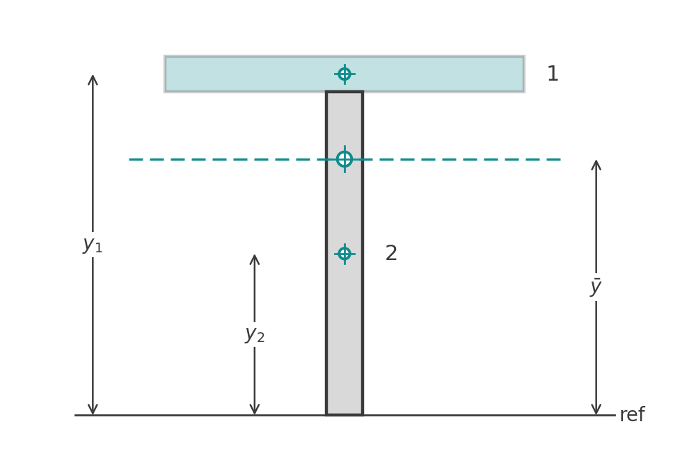
For built-up and rolled sections the integral becomes a sum over simple pieces:
$$ \bar{y} = \frac{\sum A_i \, y_i}{\sum A_i} $$
where
\( A_i \) is the area of piece \( i \)
\( y_i \) is the distance from the reference axis to the centroid of piece \( i \)
The procedure:
- Pick a reference axis. The bottom face is the usual choice for \( \bar{y} \), the left or back face for \( \bar{x} \).
- Divide the section into rectangles, triangles and circles.
- Write down each piece's area and the distance from the reference axis to its own centroid.
- Multiply, sum, and divide by the total area.
Holes and cut-outs are handled by giving them a negative area. The sum then subtracts their first moment, which is exactly right.
Worked example: T section
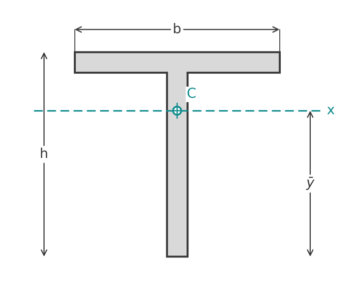
A T section has a 200 mm by 20 mm flange on top of a 180 mm by 20 mm web, 200 mm deep overall. Measuring from the bottom of the web:
- Flange: \( A_1 = 200 \times 20 = 4000 \text{ mm}^2 \), centroid at \( y_1 = 180 + 10 = 190 \) mm
- Web: \( A_2 = 180 \times 20 = 3600 \text{ mm}^2 \), centroid at \( y_2 = 90 \) mm
$$ \bar{y} = \frac{4000 \times 190 + 3600 \times 90}{4000 + 3600} = \frac{760\,000 + 324\,000}{7600} = 142.6 \text{ mm} $$
The centroid sits 142.6 mm above the bottom of the web and 57.4 mm below the top of the flange. It lies in the web, 37.4 mm below the underside of the flange, which is normal for a T with a wide flange. By symmetry \( \bar{x} \) is on the web centreline. In a stress check this section has two different extreme fibre distances, so it gets two section moduli, as covered in the section modulus guide.
Centroid formulas for common shapes
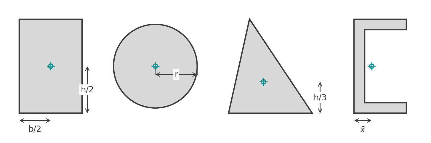
In each case the position is quoted from the bottom edge for \( \bar{y} \) and from the left edge for \( \bar{x} \), unless noted.
Rectangle
$$ \bar{x} = \frac{b}{2}, \qquad \bar{y} = \frac{h}{2} $$
Circle and hollow circle
The centroid is the centre, for both a solid circle of radius \( r \) and a tube, provided the tube is concentric. A semicircle is the common exception: its centroid lies \( 4r / 3\pi \approx 0.424 r \) above the flat edge.
Triangle
For any triangle, symmetric or not, the centroid is one third of the height above the base:
$$ \bar{y} = \frac{h}{3} $$
Horizontally it is the average of the three vertex x coordinates, \( \bar{x} = (x_1 + x_2 + x_3)/3 \). For a right triangle with the right angle at the origin that gives \( \bar{x} = b/3 \). For an isosceles triangle it is \( b/2 \) by symmetry.
Symmetrical I or H section
$$ \bar{x} = \frac{b}{2}, \qquad \bar{y} = \frac{d}{2} $$
Unsymmetrical I section
With a top flange \( b_t \times t_t \), a web \( h_w \times t_w \) and a bottom flange \( b_b \times t_b \), measured from the bottom face:
$$ \bar{y} = \frac{b_t t_t \left( d - t_t/2 \right) + h_w t_w \left( t_b + h_w/2 \right) + b_b t_b \left( t_b/2 \right)}{b_t t_t + h_w t_w + b_b t_b} $$
This is the composite formula written out for three rectangles. The full worked example, including the moment of inertia that follows, is on our moment of inertia of an I beam page: for a 300 mm deep section with a 200 mm top flange and a 120 mm bottom flange, \( \bar{y} \) comes out at 172.9 mm.
T section
With flange \( b \times t_f \) on top of a web \( h_w \times t_w \), measured from the bottom of the web:
$$ \bar{y} = \frac{b t_f \left( h_w + t_f/2 \right) + h_w t_w \left( h_w/2 \right)}{b t_f + h_w t_w} $$
Channel or U section
\( \bar{y} \) is at mid-depth by symmetry. \( \bar{x} \), measured from the back of the web, comes from the web plus the two flange outstands. For a channel with a 200 mm by 10 mm web and two 50 mm by 10 mm flange outstands:
- Web: \( 2000 \text{ mm}^2 \) at \( x = 5 \) mm
- Each outstand: \( 500 \text{ mm}^2 \) at \( x = 10 + 25 = 35 \) mm
$$ \bar{x} = \frac{2000 \times 5 + 2 \times 500 \times 35}{3000} = \frac{45\,000}{3000} = 15.0 \text{ mm} $$
The centroid is inside the web, 5 mm clear of its inner face. That is typical of channels and is the reason an axial load applied through a channel's web induces bending about the weak axis.
Angle
Both coordinates need finding. Split the angle into two rectangles, one leg plus the remainder of the other, and apply the sum twice. Our angle section calculator does this and carries the result through to the moments of inertia.
Sections with holes
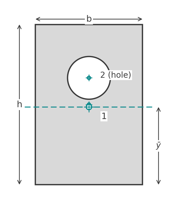
Treat a hole as a piece with negative area. For a 200 mm by 300 mm rectangle with an 80 mm diameter hole centred 200 mm above the bottom face:
- Rectangle: \( A_1 = 60\,000 \text{ mm}^2 \) at \( y_1 = 150 \) mm
- Hole: \( A_2 = -\pi \times 40^2 = -5027 \text{ mm}^2 \) at \( y_2 = 200 \) mm
$$ \bar{y} = \frac{60\,000 \times 150 - 5027 \times 200}{60\,000 - 5027} = \frac{7\,994\,600}{54\,973} = 145.4 \text{ mm} $$
Removing material above mid-height pulls the centroid down by 4.6 mm. The same trick handles bolt holes in a net section, the void in a box girder, or a cored precast unit.
Centroid and neutral axis are not always the same
For a single homogeneous material in the elastic range the neutral axis passes through the centroid, and the centroid formulas above are all you need. Two cases break that:
- Composite sections. A steel beam with a concrete slab, or a reinforced concrete section, has materials of different stiffness. The neutral axis passes through the centroid of the transformed section, where each material's area is scaled by its modular ratio. AS 3600 and EN 1992-1-1 both work this way for cracked and uncracked RC sections; our RC neutral axis calculator to AS 3600 shows the cracked case.
- Plastic design. At full plasticity the neutral axis is the equal-area axis, which splits the section into two halves of equal area rather than equal first moment. For a T section it sits well above the elastic centroid.
For odd shapes, cold-formed profiles and anything with curves, hand splitting gets tedious. Section property software and polygon-based routines compute the centroid by summing over the outline, which is the same formula applied to many small pieces.
Run it in CalcTree
The composite section properties calculator runs the composite method live. The composite method is a short loop of areas and lever arms, so it suits a live, checkable CalcTree page: list the pieces, let the centroid, moment of inertia and section moduli update together, and keep the working visible for review. The rectangular section geometric properties template is a starting point, and the template library has calculators for angles, hollow sections and reinforced concrete sections.