
What dead load and live load are, typical values from AS/NZS 1170.1 and EN 1991-1-1, how to turn them into beam and column loads, and how to combine them.
Dead load and live load are the two gravity loads every structure is designed for. Dead load is the permanent weight of the structure and whatever is fixed to it. Live load is the variable weight of the people, furniture, stock and vehicles that use it. Getting both right is the first step of any design, because every action that follows, from the beam moment to the footing bearing pressure, scales with them.
This guide defines each load, shows how to calculate dead load from a floor build-up, gives typical live load values from AS/NZS 1170.1 and EN 1991-1-1, and works an office floor beam through to factored design loads under both codes.
What is dead load?
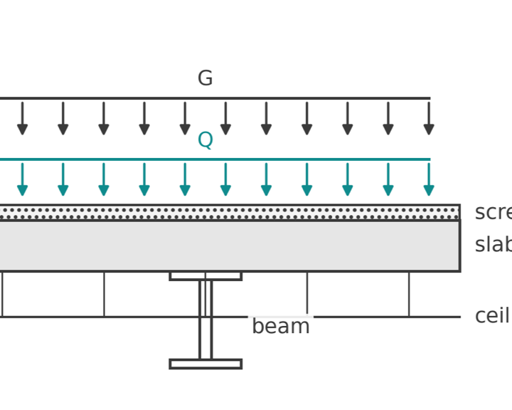
Dead load is the permanent action: the self weight of the structure plus everything fixed to it for its whole life. AS/NZS 1170 calls it \( G \); the Eurocodes call it \( G_k \). It includes:
- the structural members themselves: slabs, beams, columns, walls, roof framing
- floor finishes, screeds, toppings and raised floors
- ceilings, services, ducts and sprinklers hung from the structure
- permanent partitions, cladding, roofing, glazing and parapets
- fixed plant and equipment
Dead load is always present, acts vertically downward, and can be estimated with reasonable confidence from dimensions and unit weights. Where the finishes are not yet known, designers carry a superimposed dead load (SDL) allowance; the structural load calculations guide covers how to set it.
Unit weights
Both codes publish tables of unit weight: AS/NZS 1170.1 Appendix A and EN 1991-1-1 Annex A. Typical values, which you should confirm against the table for your material:
- reinforced concrete: 25 kN/m³ (plain concrete about 24 kN/m³)
- structural steel: 77 to 78.5 kN/m³
- softwood timber: roughly 4 to 6 kN/m³ depending on species and moisture
- clay brick masonry: about 19 to 20 kN/m³
- water: 9.81 kN/m³, often rounded to 10
Because dead load is more predictable than live load, both codes give it a lower load factor at the ultimate limit state.
What is live load?
Live load, or imposed load, is the variable action that comes from using the building: people, furniture, movable partitions, stored goods, and vehicles in car parks. AS/NZS 1170 calls it \( Q \); the Eurocodes call it \( Q_k \). It varies in magnitude and position over time, so the code value is a characteristic load that is unlikely to be exceeded, applied wherever it produces the worst effect.
Live load does not include wind, snow or earthquake. Those are separate actions with their own standards (AS/NZS 1170.2, 1170.3 and 1170.4, or EN 1991-1-4, EN 1991-1-3 and EN 1998) and their own load factors. A roof snow load, for example, is handled by a calc such as the EN 1991-1-3 snow load on a roof rather than as a live load.
Codes give live load two ways for each occupancy: a uniformly distributed load in kPa for the overall design, and a concentrated load in kN applied anywhere, which governs local effects such as a thin slab or a stair tread. Design for whichever is worse; they are not applied together.
Typical live load values
Values from AS/NZS 1170.1 Table 3.1, as uniformly distributed loads:
- residential, self-contained dwellings: 1.5 kPa
- offices for general use: 3.0 kPa
- retail shop floors: 4.0 kPa
- parking for vehicles up to 2.5 t: 2.5 kPa
- plant rooms: 5.0 kPa
- roofs not accessible except for maintenance: 0.25 kPa minimum, from \( 1.8/A + 0.12 \) with \( A \) the supported area in m²
Values from EN 1991-1-1 Table 6.2, using the recommended values (a country's National Annex may change them):
- category A, residential floors: 2.0 kPa
- category B, offices: 3.0 kPa
- category C2, areas with fixed seating: 4.0 kPa
- category C5, areas with large crowds: 5.0 kPa
- category D1, general retail: 4.0 kPa
- category F, car parks for light vehicles: 2.5 kPa
- category H, roofs accessible only for maintenance: 0.4 kPa
The two codes agree closely for offices and retail. The visible differences are residential (1.5 kPa in Australia against 2.0 kPa recommended in Europe) and maintenance roofs.
Live load reduction
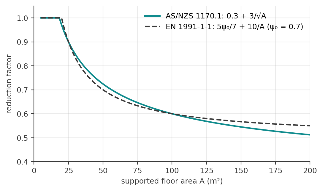
The chance that a whole large floor is loaded to its full characteristic value at once is small, so both codes let you reduce the live load on members that support a large area. AS/NZS 1170.1 Cl 3.4.2 uses a factor of \( 0.3 + 3/\sqrt{A} \), not greater than 1.0 and not less than 0.5, with \( A \) the floor area the member supports in m². EN 1991-1-1 Cl 6.3.1.2 uses \( \alpha_A = 5\psi_0/7 + A_0/A \), capped at 1.0, with \( A_0 = 10 \) m². Both exclude storage and some other occupancies, so check the conditions before applying them.
From area load to beam load to column load
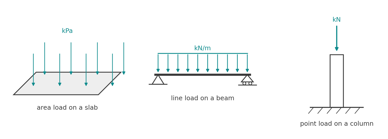
Loads are specified per square metre of floor, but beams are designed for a load per metre and columns for a force. The conversion follows the load path.
Area load
For each layer of the floor build-up, multiply the thickness by the unit weight and add the layers:
$$ g = \sum t_i \gamma_i $$
\( \rlap{g}\hspace{2.5em} \): dead load per unit area, kPa (kN/m²)
\( \rlap{t_i}\hspace{2.5em} \): thickness of layer \( i \), m
\( \rlap{\gamma_i}\hspace{2.5em} \): unit weight of layer \( i \), kN/m³
Line load
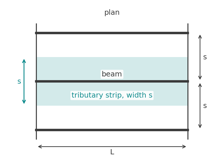
A beam carries the strip of floor halfway to the next beam on each side. That strip is its tributary width \( s \), equal to the beam spacing for a regular grid. The line load is the area load times the tributary width, plus the beam's own weight:
$$ w_G = g \, s + g_{sw}, \qquad w_Q = q \, s $$
Point load
Each beam delivers its end reaction to a column as a point load. For a simply supported beam that is half the total load on the beam, \( wL/2 \). Columns accumulate these reactions floor by floor down to the footing.
Worked example: an office floor beam
Once the factored line load is known, the beam analysis pack using Macaulay's theorem turns it into the design moment and shear for the beam, with the diagrams drawn.
A floor has 200 mm reinforced concrete slabs on steel beams at 4 m centres spanning 8 m. The build-up is a 50 mm sand-cement screed, plus an allowance of 0.5 kPa for the ceiling and services. The beam weighs about 0.8 kN/m. Occupancy is general office.
Dead load per square metre:
- slab: \( 0.200 \times 25 = 5.0 \) kPa
- screed: \( 0.050 \times 22 = 1.1 \) kPa
- ceiling and services: 0.5 kPa
- total \( g = 6.6 \) kPa
Live load for offices, \( q = 3.0 \) kPa under either code. With \( s = 4 \) m the beam line loads are:
$$ w_G = 6.6 \times 4 + 0.8 = 27.2 \text{ kN/m}, \qquad w_Q = 3.0 \times 4 = 12.0 \text{ kN/m} $$
The beam supports \( 8 \times 4 = 32 \) m² of floor, so a reduction would be allowed: \( 0.3 + 3/\sqrt{32} = 0.83 \) under AS/NZS 1170.1, or \( 0.5 + 10/32 = 0.81 \) under EN 1991-1-1 with \( \psi_0 = 0.7 \). This example keeps the full 12.0 kN/m to stay conservative.
Ultimate limit state to AS/NZS 1170.0 Cl 4.2.2, with the \( 1.2G + 1.5Q \) combination:
$$ w^* = 1.2 \times 27.2 + 1.5 \times 12.0 = 50.6 \text{ kN/m} $$
The dead-load-only case \( 1.35G = 36.7 \) kN/m is smaller, so \( 1.2G + 1.5Q \) governs. For the 8 m simply supported span:
$$ M^* = \frac{w^* L^2}{8} = \frac{50.6 \times 8^2}{8} = 405 \text{ kNm}, \qquad V^* = \frac{w^* L}{2} = 202 \text{ kN} $$
The same beam to EN 1990 Eq. 6.10 with \( \gamma_G = 1.35 \) and \( \gamma_Q = 1.5 \):
$$ w_{Ed} = 1.35 \times 27.2 + 1.5 \times 12.0 = 54.7 \text{ kN/m}, \qquad M_{Ed} = \frac{54.7 \times 8^2}{8} = 438 \text{ kNm} $$
The Eurocode design moment is about 8% higher here because of the heavier factor on dead load. For deflection checks the loads are unfactored: AS/NZS 1170.0 uses \( G + \psi_s Q \) with \( \psi_s = 0.7 \) for offices, giving \( 27.2 + 0.7 \times 12.0 = 35.6 \) kN/m, while the Eurocode quasi-permanent combination \( G + \psi_2 Q \) with \( \psi_2 = 0.3 \) gives 30.8 kN/m. Each beam end then delivers \( 50.6 \times 8/2 = 202 \) kN (AS ultimate) to its column. How those loads become shear and moment along the beam is covered in shear force and bending moment diagrams.
Load combinations and factors
With only dead and live load acting, the combinations are:
- AS/NZS 1170.0 Cl 4.2.2 (ultimate): \( 1.35G \) and \( 1.2G + 1.5Q \). Serviceability (Cl 4.3): \( G + \psi_s Q \) for short-term effects and \( G + \psi_l Q \) for long-term effects, with \( \psi_s = 0.7 \) and \( \psi_l = 0.4 \) for residential and office floors from Table 4.1.
- EN 1990 Eq. 6.10 (ultimate): \( 1.35G_k + 1.5Q_k \). Serviceability: characteristic \( G_k + Q_k \), frequent \( G_k + \psi_1 Q_k \) and quasi-permanent \( G_k + \psi_2 Q_k \), with \( \psi_0 = 0.7 \), \( \psi_1 = 0.5 \) and \( \psi_2 = 0.3 \) for categories A and B from Table A1.1.
Where wind or earthquake also act, the live load appears in those combinations with a reduced combination factor, because the full live load is unlikely to coincide with the design storm.
Direction and units
Both loads act vertically downward under gravity. On a pitched roof, a dead load given per square metre of slope needs converting to plan area before it is combined with loads given on plan: divide by the cosine of the pitch. A 0.6 kPa roof build-up at 20° pitch is \( 0.6 / \cos 20^\circ = 0.64 \) kPa on plan. Roof live loads are already given on plan.
In SI the units are kN/m³ for unit weight, kPa (equal to kN/m²) for area loads, kN/m for line loads and kN for point loads. One kPa is about 20.9 psf, which is handy when reading US references.
Run it in CalcTree
The beam analysis pack using Macaulay's theorem takes the factored line load from a take-down like this one through to the design moment and shear. A floor load take-down like the one above can be built as a live CalcTree page: list the build-up layers, pick the occupancy, set the beam spacing and span, and the line loads, combinations and design actions follow, with every step visible for a checker. Start from the template library.





