
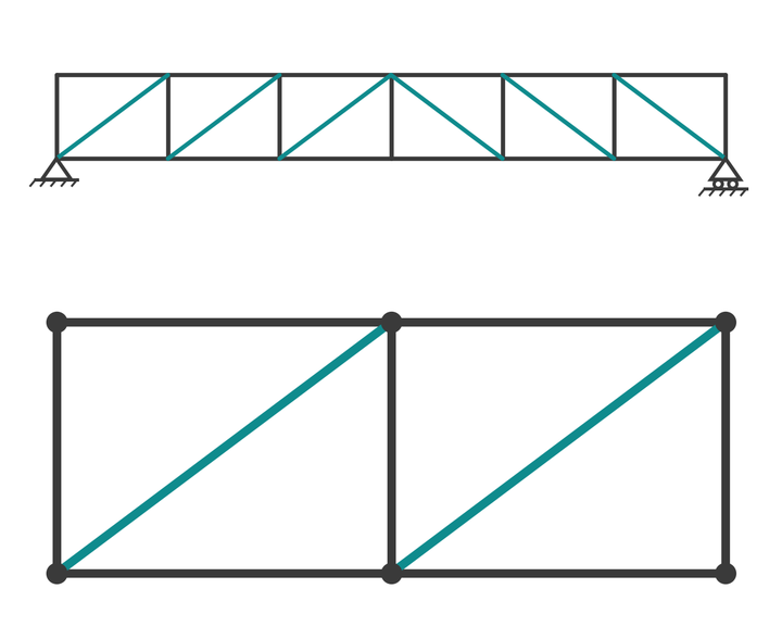
How a Howe truss works, why its diagonals are in compression and verticals in tension, and a worked example by the method of joints and sections.
The Howe truss is a parallel-chord truss whose diagonals slope up toward mid-span, the mirror image of a Pratt truss. Under gravity load its diagonals are in compression and its verticals are in tension, which made it the natural choice for timber bridges and roofs where the diagonals could be heavy timber struts and the verticals iron rods. It remains common in timber roof trusses, timber footbridges and some steel roof girders.
This guide explains how a Howe truss works, solves a six-panel example by the method of joints and the method of sections, and shows which members carry tension and which compression. For the basics of truss analysis, read our truss analysis and design guide first. The Pratt truss page covers the opposite arrangement.
What is a Howe truss?
A Howe truss has a top chord, a bottom chord, a vertical at every panel point and one diagonal per panel. In the left half of the span each diagonal runs from the bottom of a vertical up to the top of the next vertical toward the centre; the right half mirrors it. From the side, the diagonals form an inverted V with its apex at mid-span.
William Howe patented the form in 1840. Its advantage in his day was material: timber is good in compression but poor at tension connections, and wrought iron rods were good in tension and easy to tighten with threaded ends. So the diagonals were timber struts and the verticals were iron tie rods. That logic is why a Howe truss is still the conventional pattern for timber roof trusses and timber bridges, and why the pitched roof version is often simply called a Howe roof truss.
In steel, where a slender tension diagonal is cheaper than a stocky compression one, the Pratt arrangement is usually preferred for a bridge. The Howe still appears where the diagonals are needed as compression struts anyway, or where the load direction reverses.
Static system
The members are idealised as pin-ended and weightless, with loads applied only at the joints, so each member carries axial force alone. A single span is supported on a pin and a roller, giving three reaction components, and is statically determinate when
$$ m + r = 2j $$
where \(m\) is the number of members, \(r\) the number of reaction components and \(j\) the number of joints.
The example has 25 members, 3 reactions and 14 joints, so \(25 + 3 = 28 = 2 \times 14\) and the truss is determinate.
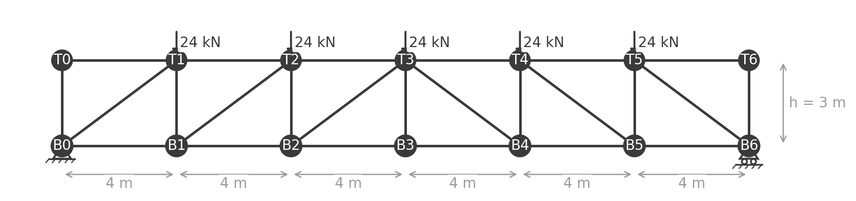
The example spans 24 m in six panels of 4 m with a depth of 3 m, so each diagonal is a 3-4-5 triangle: 5 m long, with \(\sin\theta = 0.6\) and \(\cos\theta = 0.8\). This time the load arrives on the top chord, as it would from purlins on a roof girder: 24 kN at each of the five interior top chord joints. Any load at the end joints T0 and T6 passes straight down the end posts to the supports and is omitted.
Howe truss analysis
Every number in this section can be reproduced in the truss analysis calculator: choose Howe, a 24 m span, 3 m depth, six panels and 24 kN on the top chord, and read the reactions and member forces off the page.
Reaction forces
The applied load totals \(5 \times 24 = 120\) kN, symmetric about mid-span, so
$$ R_A = R_B = \frac{120}{2} = 60 \text{ kN} $$
For an unsymmetric load, take moments about one support for the other reaction, then vertical equilibrium for the remainder.
Method of joints
Start at joint T0. It has no load and only two members, the end post B0T0 and the top chord T0T1, which are perpendicular. Each must therefore be zero: \(F_{T0T1} = 0\) and \(F_{B0T0} = 0\). With the load on the top chord, the end posts and the first top chord panel of a Howe truss are zero-force members.
Now joint B0, where the reaction of 60 kN acts up and the unknowns are the diagonal B0T1 and the bottom chord B0B1. With tension positive, vertical equilibrium gives
$$ 60 + F_{B0T1} \sin\theta = 0 \quad\Rightarrow\quad F_{B0T1} = -\frac{60}{0.6} = -100 \text{ kN} $$
The diagonal is in compression: it pushes down on the support joint. Horizontal equilibrium gives the bottom chord:
$$ F_{B0B1} + F_{B0T1} \cos\theta = 0 \quad\Rightarrow\quad F_{B0B1} = 100 \times 0.8 = 80 \text{ kN} $$
At joint T1 the diagonal B0T1 pushes up and to the right with components 80 kN horizontal and 60 kN vertical, and the 24 kN load acts down. Vertical equilibrium gives the vertical B1T1:
$$ 60 - 24 - F_{B1T1} = 0 \quad\Rightarrow\quad F_{B1T1} = 36 \text{ kN} $$
which is tension: the vertical hangs the top chord joint from the bottom chord. Horizontal equilibrium at T1 gives the top chord \(F_{T1T2} = -80\) kN in compression.
Method of sections
For a member deep in the span, cut through the second panel so the cut crosses T1T2, B1T2 and B1B2, and keep the left part with the reaction and the 24 kN load at T1.
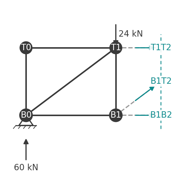
Moments about T2, where the top chord and the diagonal meet, isolate the bottom chord:
$$ F_{B1B2} \times 3 = 60 \times 8 - 24 \times 4 \quad\Rightarrow\quad F_{B1B2} = \frac{384}{3} = 128 \text{ kN} $$
Moments about B1, where the diagonal and the bottom chord meet, isolate the top chord:
$$ F_{T1T2} \times 3 = -60 \times 4 \quad\Rightarrow\quad F_{T1T2} = -80 \text{ kN} $$
Vertical equilibrium of the free body gives the diagonal:
$$ 60 - 24 + F_{B1T2} \sin\theta = 0 \quad\Rightarrow\quad F_{B1T2} = -\frac{36}{0.6} = -60 \text{ kN} $$
The negative sign confirms compression. Note that the sign of the diagonal is decided by its slope: the panel shear here is the same 36 kN it would be in a Pratt truss with the same loads, but a diagonal rising toward mid-span can only resist an upward shear on the left face by pushing, so it is in compression.
Compression and tension members
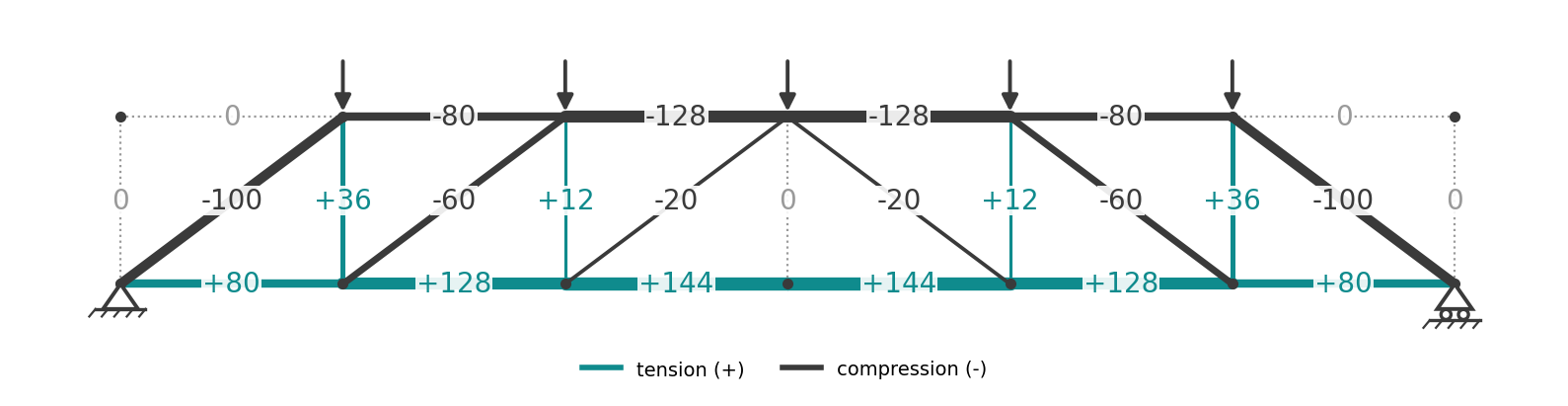
The full set of member forces, with tension positive:
- Bottom chord: 80, 128, 144, 144, 128, 80 kN, tension.
- Top chord: 0, 80, 128, 128, 80, 0 kN, compression. The 128 kN peak is at mid-span.
- Diagonals, from the support inward: 100, 60, 20 kN, all compression, mirrored on the right.
- Verticals, from the support inward: 0, 36, 12 kN, tension, with the centre vertical at zero. The end posts are zero-force members.
So the Howe signature under gravity load is compression diagonals and tension verticals, the reverse of the Pratt. Because the top chord is loaded here, the first top chord panel is unstressed and the bottom chord starts at 80 kN right at the support, where a bottom-loaded Pratt truss starts at zero. The compression diagonals are 5 m long against 3 m for the verticals, so the buckling-prone members are the longer ones. That is the trade-off that favours timber struts or hollow steel sections for the diagonals.
A design note on the verticals: a 3 m tension member carrying 36 kN is trivial in steel, which is why historic Howe bridges used threaded rods, and why, in a modern timber Howe truss, the verticals are often steel rods or bolts rather than timber.
Member design and code references
- Compression diagonals and chords in steel: EN 1993-1-1 clause 6.3.1, \(N_{b,Rd} = \chi A f_y / \gamma_{M1}\). AS 4100 clauses 6.2 and 6.3, \(N_s = k_f A_n f_y\) and \(N_c = \alpha_c N_s\).
- Tension verticals and bottom chord in steel: EN 1993-1-1 clause 6.2.3; AS 4100 clause 7.2.
- Timber members: EN 1995-1-1 for the Eurocode route and AS 1720.1 for Australia, with the compression strut check governed by the diagonal's slenderness.
- Load combinations: EN 1990 or AS/NZS 1170.0. Roof loads from EN 1991-1-1 and EN 1991-1-3 or AS/NZS 1170.1 and AS/NZS 1170.3. Our structural load calculations guide walks through the AS/NZS 1170 load build-up.
Advantages and disadvantages
Advantages:
- Suits materials that are strong in compression and awkward in tension, which is why it is the standard timber truss.
- Tension verticals can be slender rods that are easy to tighten and adjust for camber.
- With a top chord load, the end posts carry nothing and the chord forces start low at the support.
- Same simple geometry and repeatable connections as a Pratt.
Disadvantages:
- The longest web members are in compression, so in steel the diagonals need stockier sections than Pratt diagonals of the same length.
- Compression diagonals need a buckling check in both planes, and often lateral restraint at mid-length on long spans.
- More members and joints than a Warren truss.
Howe truss FAQ
What is the difference between a Howe truss and a Pratt truss?
Only the slope of the diagonals. Howe diagonals rise toward mid-span and are in compression under gravity load, with the verticals in tension. Pratt diagonals fall toward mid-span and are in tension, with the verticals in compression.
Why is the Howe truss used for timber?
Timber carries compression well and makes poor tension splices, so putting the diagonals in compression and using steel rods for the tension verticals plays to each material's strength.
Which members of a Howe truss are in tension?
Under downward load on a simply supported span, the bottom chord and the verticals. The top chord and the diagonals are in compression. The signs reverse for uplift.
Can a Howe truss be used for a roof?
Yes, and it is the most common pattern for a pitched timber roof truss. The pitched version has sloping top chords meeting at a ridge, with the same diagonal direction and the same compression-strut, tension-tie logic.
Run it in CalcTree
The truss analysis calculator runs this example live, and switches between the Warren, Pratt, Howe and K forms on the same span. The equilibrium steps above can be built as a live CalcTree page with span, panel count, depth and joint loads as inputs and every member force as a checkable output, so a change in roof load flows straight through to the governing compression diagonal. Link it to the AS 4100 steel member check or the AS 1720.1 timber column check to size the struts, or browse the template library.





