Free Transformer Short Circuit Calculator. Step-by-step, engineering-grade tool with downloadable report.

This template is not available yet. You can sign up and create it yourself!
Or let us know if you'd like to be notified when it’s ready:
No items found.
No items found.
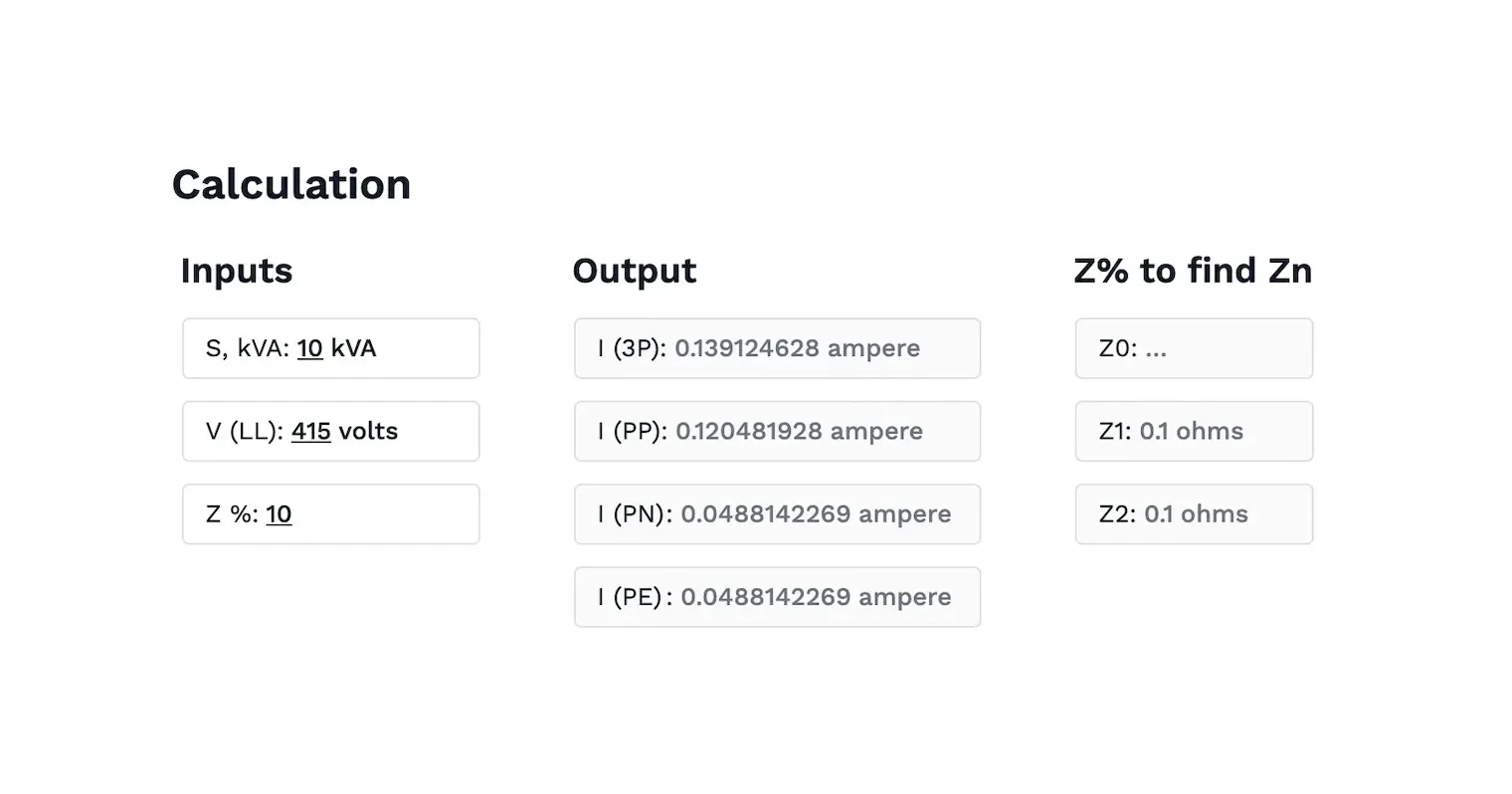
About this Transformer Short Circuit Calculator
The Transformer Short Circuit Calculator is a practical tool that determines the short circuit current on the secondary side of a transformer. By inputting the transformer’s kVA rating, secondary voltage, and impedance percentage, the calculator delivers fast and accurate results—making it easy to assess fault conditions and system protection requirements.
This calculator is ideal for users who want to duplicate and customize calculation templates for their next project:
- Engineers designing transformer protection systems or conducting fault current analysis.
- Maintenance technicians evaluating equipment safety under high-load or fault scenarios.
- Students learning about transformer behavior, impedance, and short-circuit dynamics in power systems.
Whether you're comparing multiple transformers or validating protection settings, this tool helps quickly assess if a transformer and associated components can handle short-circuit stress.
Introduction to Short Circuit Calculations
In electrical systems, a short circuit occurs when an unintended low-resistance path forms—causing a sharp rise in current. This sudden surge can severely damage transformers, switchgear, and conductors if not properly managed. Accurate short circuit calculations are essential for anticipating these conditions and designing adequate protection.
The short circuit current depends primarily on three transformer parameters:
- kVA rating – the apparent power capacity
- Secondary voltage – the voltage at the output winding
- Impedance percentage – the internal opposition to fault current flow
Using these values, engineers estimate the maximum fault current that could occur during a fault scenario. This serves as a foundation for selecting protection devices and ensuring the transformer can operate safely under fault conditions. Whether the system is single-phase or three-phase, these calculations are central to power system design.
Calculation Methods and Formulas
There are two commonly used formulas depending on the system type:
For three phase systems, the following formula is commonly used to determine the fault current:
$$ I_{\text{Fault (kA)}} = \frac{\text{MVA} \times 10^3}{\sqrt{3} \times V_{\text{Secondary}}} $$
Here, \( I_{\text{Fault (kA)}} \) represents the short circuit current in kiloamperes, \(MVA\) is the transformer rating in Mega Volt-Amperes, and \( V_{\text{Secondary}}\) is the secondary voltage in volts. This formula allows you to quickly calculate the maximum current that could flow through the secondary side of the transformer during a fault event.
For single-phase systems, the formula is adjusted to reflect the absence of three-phase power, typically using:
$$ I_{\text{Fault (A)}} = \frac{\text{kVA} \times 1000}{V_{\text{Secondary}}} $$
In both cases, the transformer’s impedance percentage must be factored in to refine the final result. Typically, engineers use a base current derived from the kVA and voltage, then divide it by the per-unit impedance to calculate the fault current.
A common assumption used here is the infinite bus model—which treats the primary side as having zero impedance. This models a worst-case condition, ensuring the calculated fault current is conservative and sufficient for safety planning.
Engineering templates
Common calculators
Design guides
FAQs
Why is it important to calculate the short circuit current of a transformer?
Calculating transformer short circuit current ensures that protective devices—like fuses and circuit breakers—are properly rated for the worst-case electrical fault. If these devices are undersized, they may fail to interrupt the fault in time, leading to catastrophic equipment failure or fire.
Fault current is also a benchmark for:
- System stability
- Thermal stress on conductors
- Arc flash hazard analysis
- Transformer withstand ratings
Engineers use this information to select equipment and build systems that are resilient under fault conditions.
How does transformer impedance affect short circuit current?
Transformer impedance directly limits the short circuit current. A lower impedance allows more current to flow during a fault, increasing the stress on the system. A higher impedance, on the other hand, restricts fault current but can affect voltage regulation.
The transformer's impedance value, usually given as a percentage, is used alongside the kVA rating to model how much current will flow during a fault. This is especially important when comparing transformers or specifying fault withstand capabilities for downstream equipment.
What factors should be considered when selecting protective devices for transformers?
When selecting protective devices, consider the transformer's short circuit current, the duration of the fault, and the potential impact on both the transformer and the connected electrical system. Properly rated protection ensures safety and minimizes equipment damage.
Resources
Alternative methods for performing these calculations can be found in textbooks such as Electrical Power Systems by C.L. Wadhwa or Power System Analysis by Hadi Saadat, which provide detailed insights into short circuit analysis and transformer behavior.
Learn about the benefits of using CalcTree on engineering projects!