
Strut and tie model calculator in Python: truss forces and node stresses for deep beams and four-pile caps, drawn to scale. Open a copy in your browser.

Tell us what you need, or sign up and build it yourself in minutes.
Leave your email and we'll tell you when a template for it is ready:
No items found.
No items found.
About this Strut-and-Tie Model Example
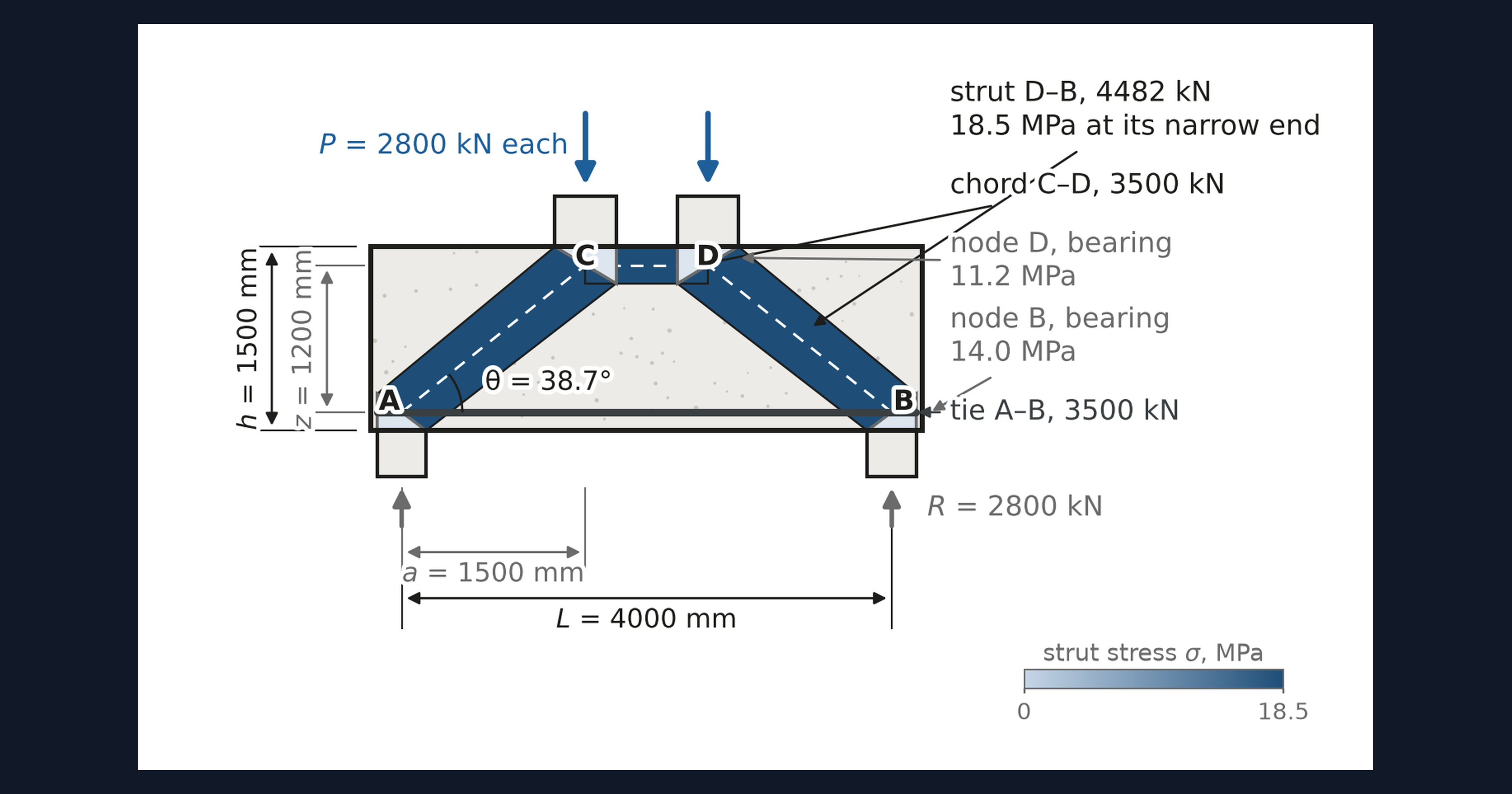
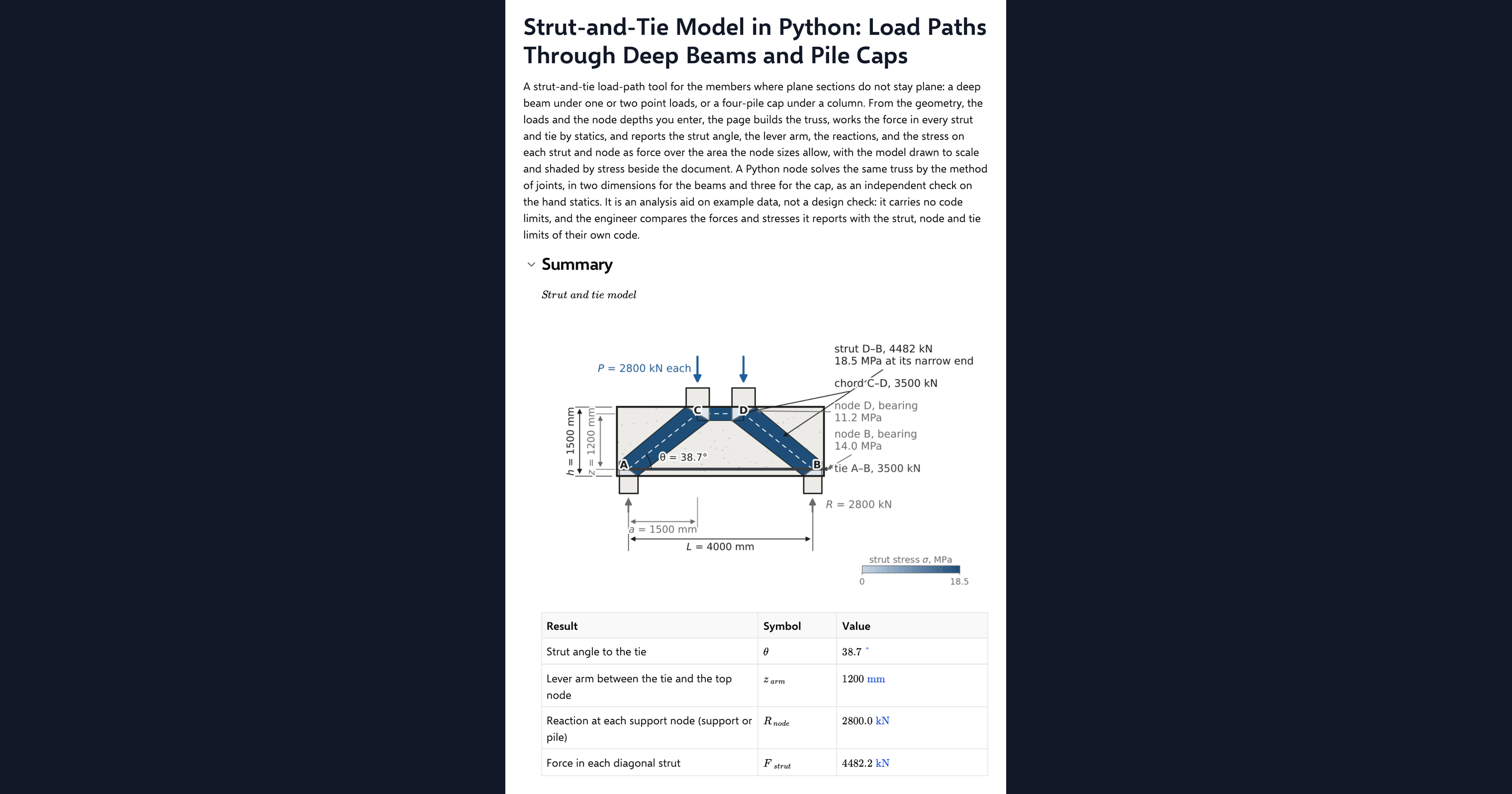
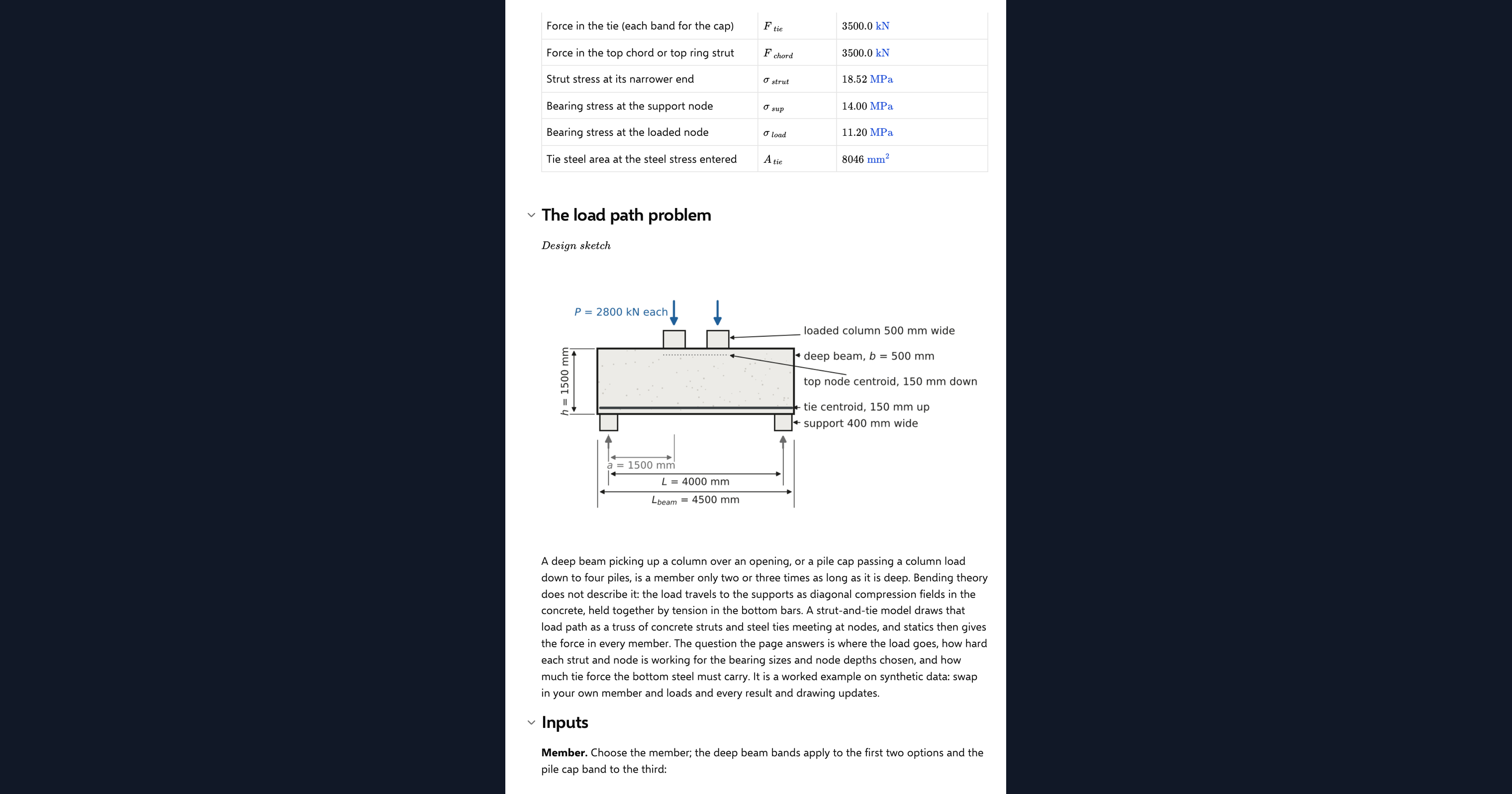
This page is a strut and tie model calculator written in Python inside a CalcTree calculation page. It covers the members where plane sections do not stay plane: a deep beam under one or two point loads, or a four-pile cap under a column. From the geometry, the loads and the node depths you enter, the page builds the truss, works the force in every strut and tie by statics, and reports the strut angle, the lever arm, the reactions and the stress on each strut and node as force over the area the nodes allow. The model is drawn to scale beside the document and shaded by stress.
- Structural engineer: get the load path, the tie force and the nodal stresses for a transfer beam or a pile cap in one place, then take the forces into whichever code you design to.
- Engineer exploring Python in calculations: see a two and three dimensional truss solved by the method of joints in plain NumPy, checked against hand statics on the same page.
- Graduate engineer learning strut-and-tie: change the depth, the span or the node widths and watch the strut angle, the forces and the drawing respond.
It reports forces and stresses only. There are no capacities, strength factors, clause references or pass and fail verdicts on the page, because those belong to the design code you work to. It is an example of what a CalcTree page can do, built with CalcTree AI, not a design method to rely on as is. The model is idealised and its limits are stated on the page. Duplicate it into your own workspace to change the inputs, read the Python, or use it as the starting point for your own analysis, and verify anything you take into a real design.
More info on Strut-and-Tie Load Paths
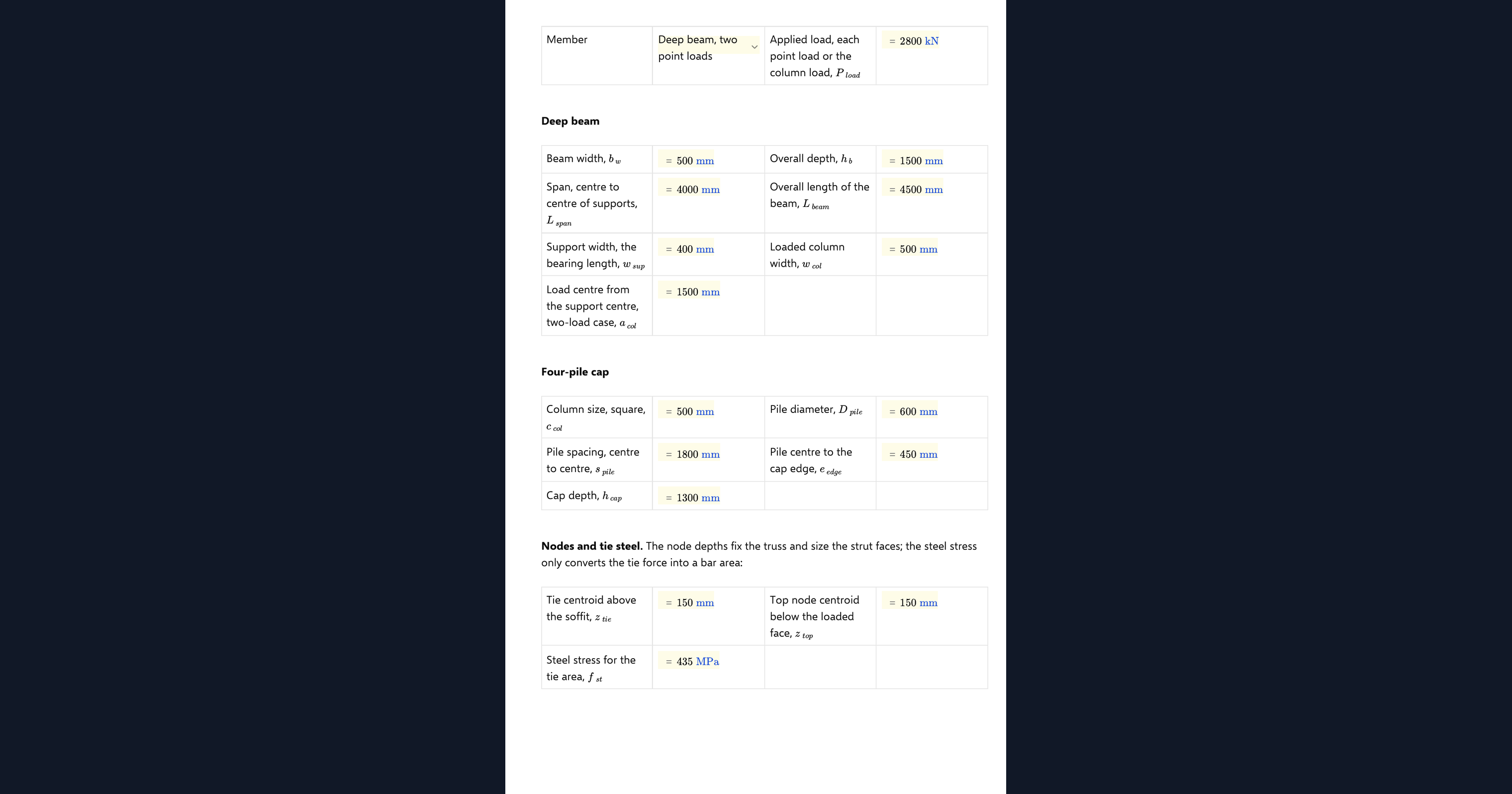
Inputs
A member dropdown chooses between a deep beam with one point load, a deep beam with two point loads and a four-pile cap under a column. You then set the span or pile spacing, the overall depth, the member width, the point load or column load, the depth of the tie centroid from the soffit, the depth of the top node, the bearing lengths at the supports and loads, the column and pile sizes for the cap, and the steel stress used to turn the tie force into a bar area. Every input carries a unit and the results follow from it.
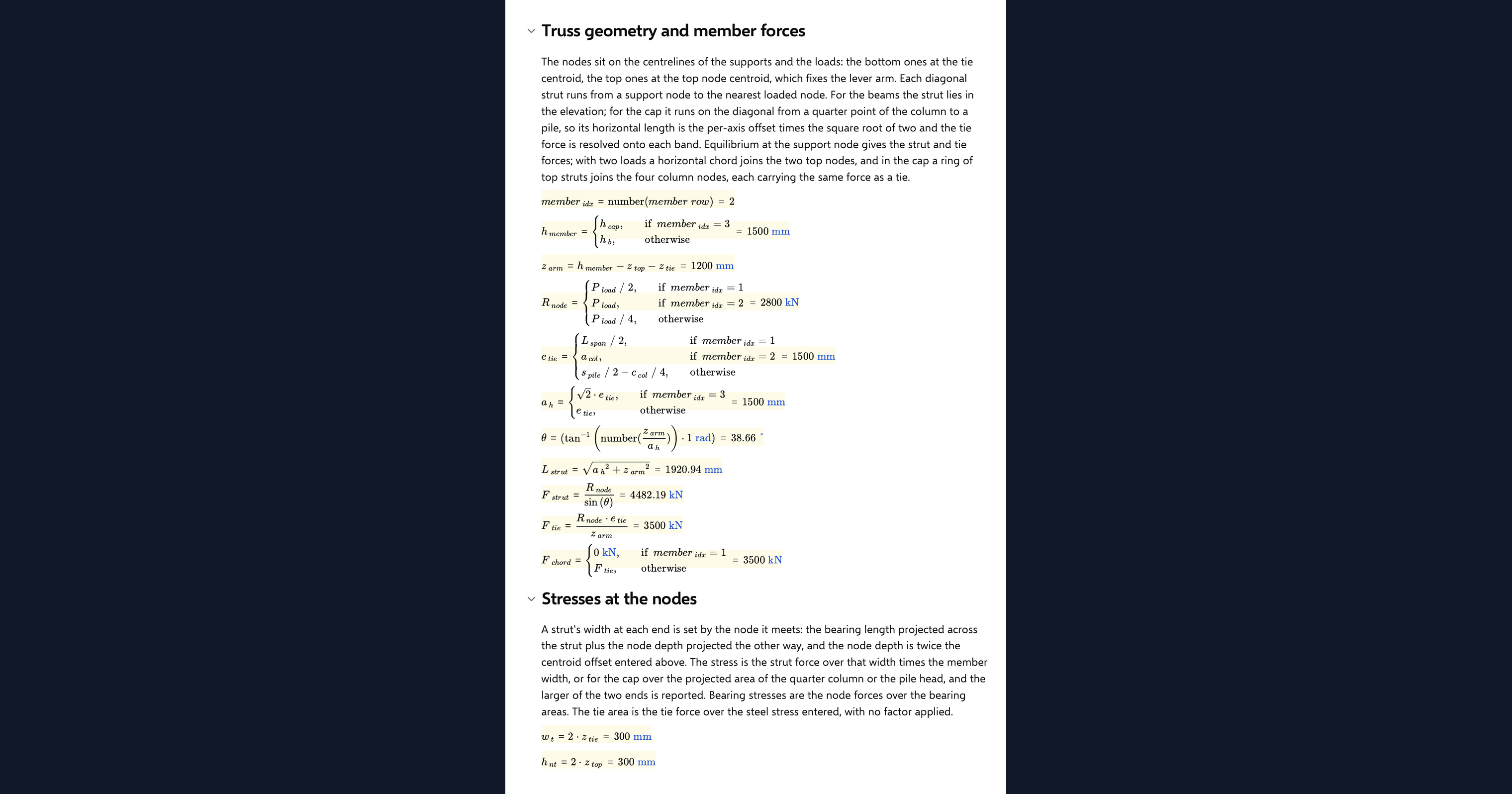
The truss by statics
The lever arm is the overall depth less the two node depths. The reaction at each support node follows from symmetry, the tie eccentricity from the load position (or the quarter points of the pile cap), and the strut angle from the arm over the horizontal run, taken on the diagonal for the cap. The strut force is the reaction over the sine of that angle, the tie force the reaction times the eccentricity over the arm, and the chord force is zero, the tie force or the top ring force depending on the member. Each of these is a visible line on the page with its formula.
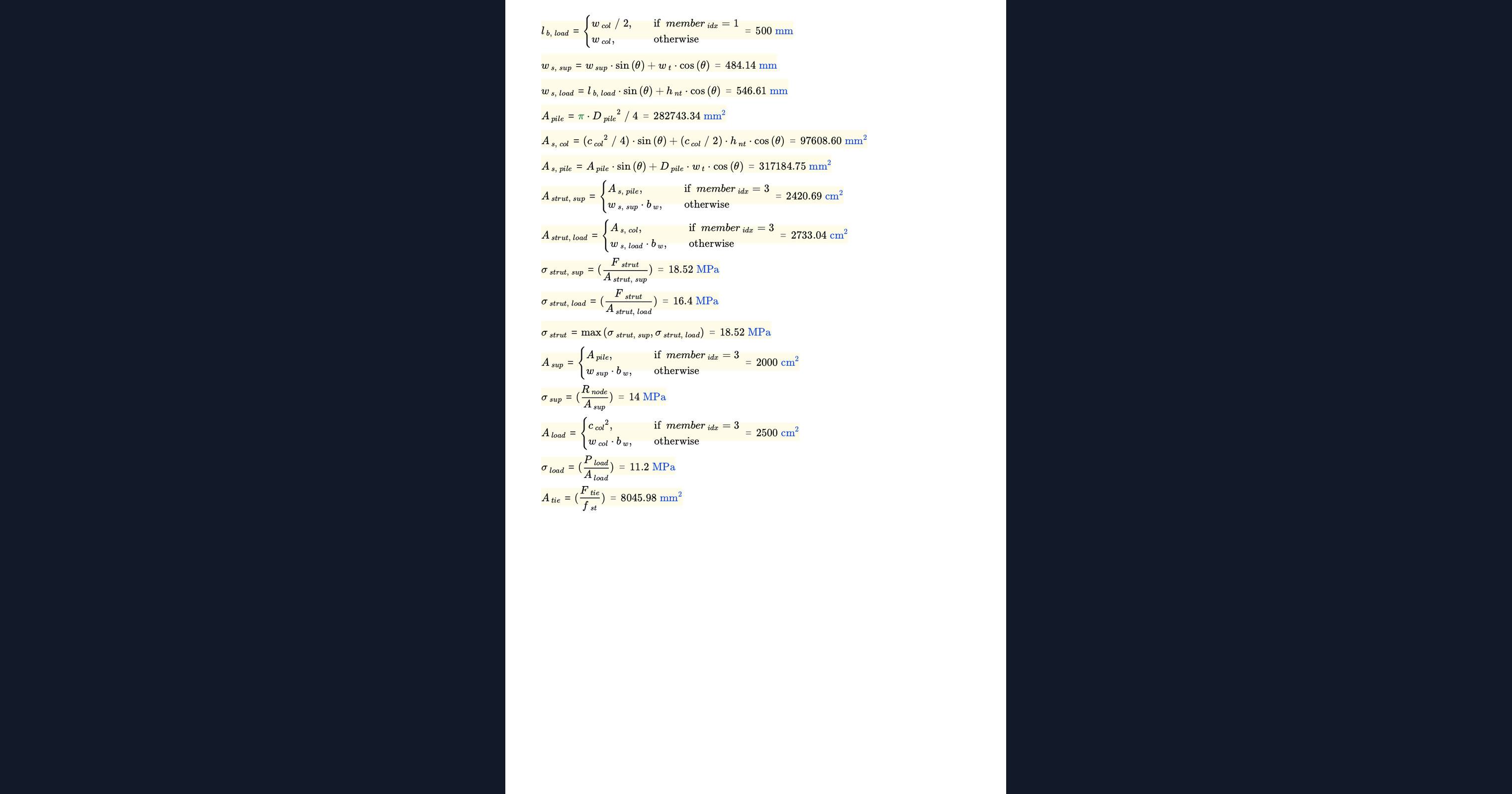
Stresses at the nodes
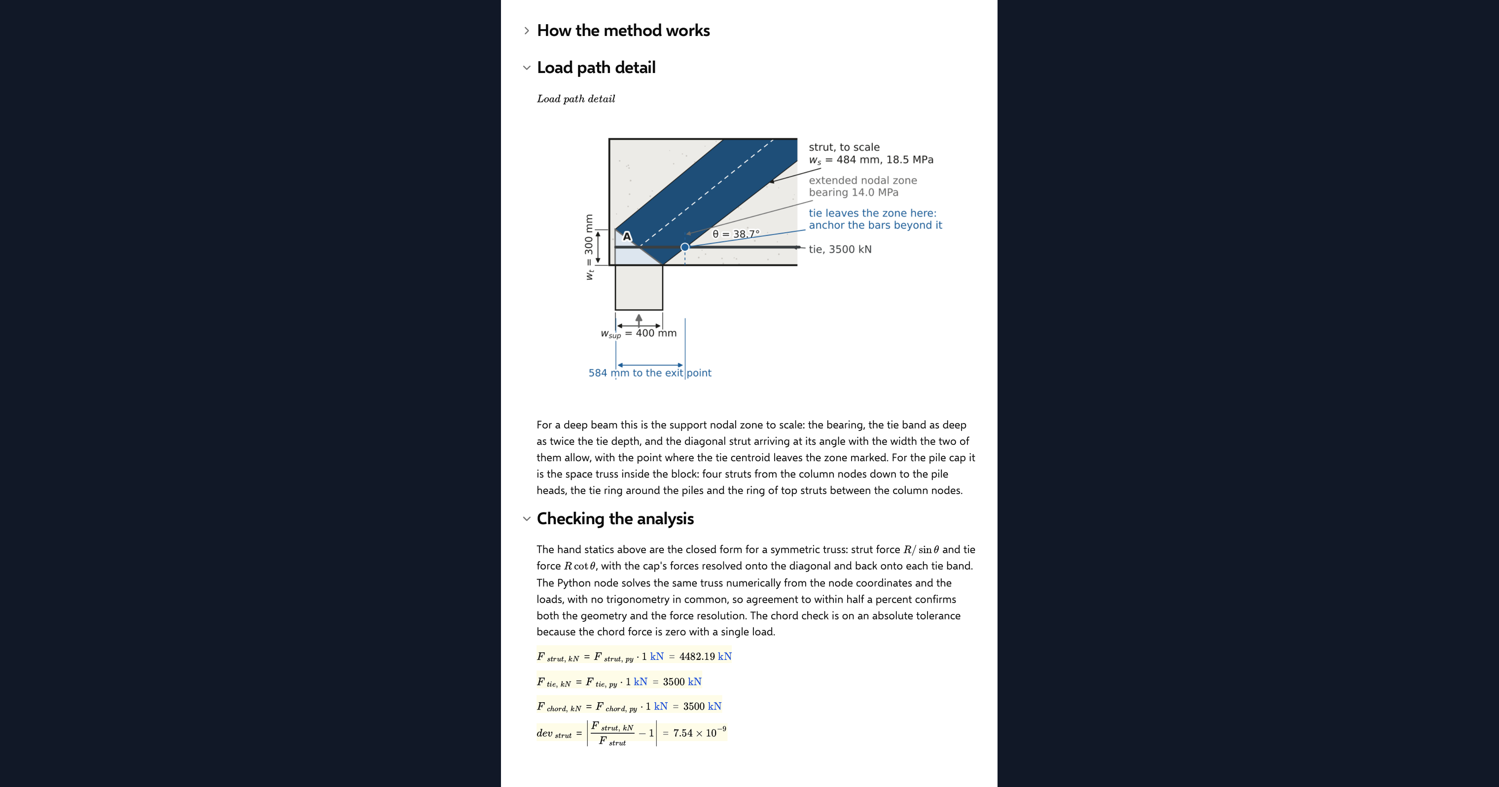
Strut widths come from the bearing length and the node depth at each end, and the cap uses the projected quarter column and pile head areas across the bearing breadth. The page divides each force by the area its node allows and reports the strut stress, the bearing stress under the load and over the support, and the tie area for the steel stress you chose. The drawings show the strut bands at those widths, shaded by stress, with the ties as bars.
Checking the analysis
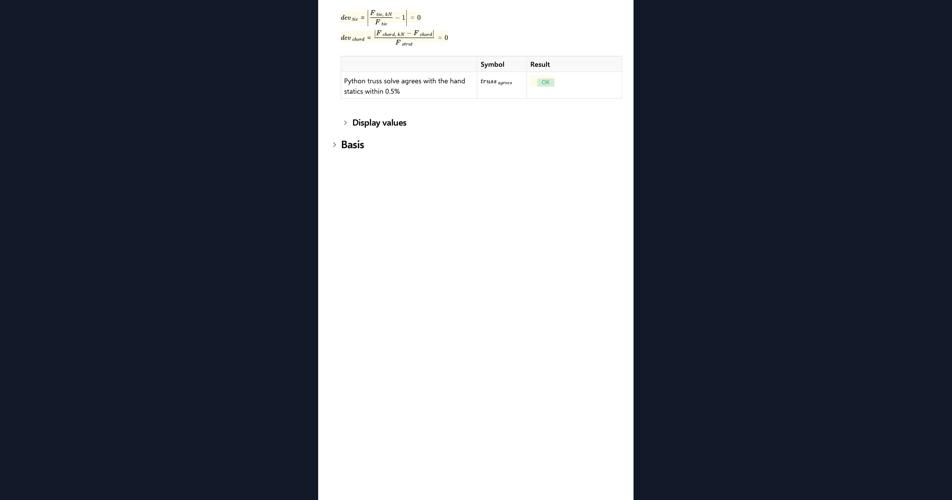
A Python node solves the same truss by the method of joints, in two dimensions for the beams and three for the cap, and reports the residual at every joint. One agreement check compares its strut, tie and chord forces with the hand statics above it, to half a percent. Nothing in the summary is a verdict; the check is there so you can trust the forces.
Python libraries used
NumPy assembles and solves the joint equilibrium equations for the two and three dimensional trusses. Matplotlib draws the design sketch, the strut-and-tie model shaded by stress and the nodal zone detail.
Common Calculation Errors to Avoid
- Treating the forces as a design check: the page gives forces and stresses, not capacities. Strut and node strengths, tie anchorage and minimum reinforcement come from the code you design to.
- A strut angle that is too flat: a shallow beam or a wide pile spacing drives the strut angle down and the strut and tie forces up. Most codes set a lower limit on the angle; check the reported value against yours.
- Guessing the node depths: the tie centroid depth and the top node depth set the lever arm, and the lever arm sets every force. Take them from the actual bar layout and bearing plate, not a rule of thumb.
- Mixing up the cap diagonal: in a four-pile cap the strut runs on the diagonal from the column quarter point to the pile, so its horizontal run is longer than the half spacing. The page does this for you; a hand check must too.
- Ignoring the bearing stress: a strut force that looks fine can still crush the node where the bearing length is short. The page reports the stress under each load and support for that reason.
- Forgetting the chord force: the two-load beam carries a top chord force equal to the tie force, and the cap carries a ring force round the top of the struts. Both need a load path of their own.
Engineering templates
Common calculators
Design guides




FAQs
What is a strut-and-tie model?
A truss drawn inside a concrete member: compression struts, tension ties and the nodes where they meet. It is the standard way to find the load path in a region where beam theory does not apply, such as a deep beam, a corbel or a pile cap, and it is what this page builds and solves.
Does this page check the member against a design code?
No. It reports the forces in every strut and tie and the stresses at every node, and it stops there. Capacities, strength reduction factors, anchorage lengths and minimum steel come from the code you work to, and the page is written so you can take its forces into any of them.
How are the strut widths and node areas chosen?
From the bearing lengths and the node depths you enter. At a support the strut width is the bearing length times the sine of the strut angle plus the node depth times its cosine, and in the pile cap the node areas are the projected quarter column and pile head across the bearing breadth. Change those inputs and the stresses and the drawing follow.
Why is there a Python node when MathJS already solves the truss?
To check it. The visible statics are the hand method, and the Python node solves the same truss by the method of joints with no knowledge of those formulas. The agreement check between them is the page's one check, and it is there so the drawing and the numbers can be trusted.
Can I use it for a different member?
The three members on the dropdown cover the common cases. For another geometry, duplicate the page and extend the Python solver with your own nodes and members; the method of joints does not care what shape the truss is.
Learn about the benefits of using CalcTree on engineering projects!