Free Logic Gates Simulator Tool. Step-by-step, engineering-grade tool with downloadable report.

This template is not available yet. You can sign up and create it yourself!
Or let us know if you'd like to be notified when it’s ready:
No items found.
No items found.
About this Logic Gates Simulator
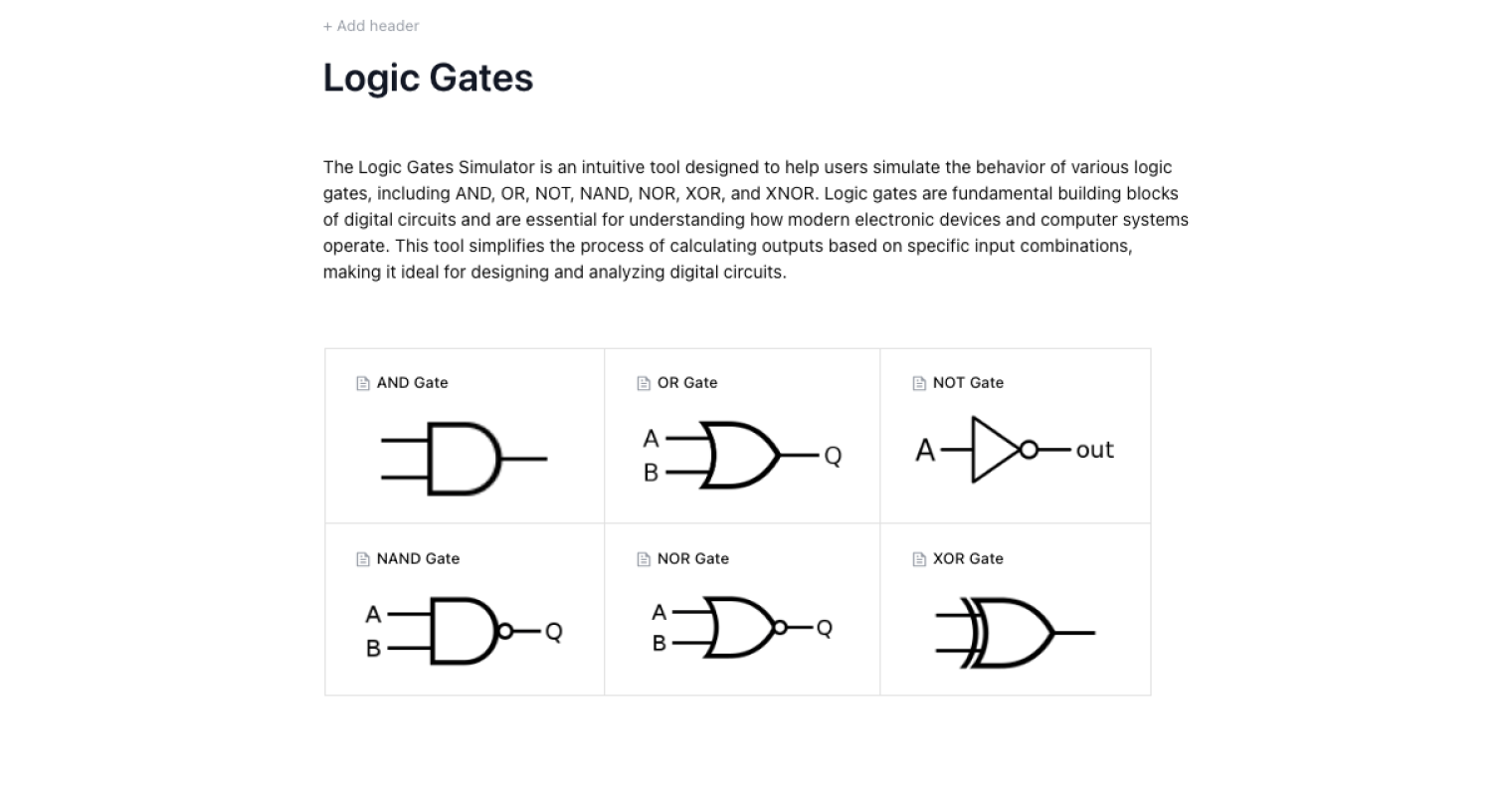
The Logic Gates Simulator is an intuitive tool designed to help users simulate the behavior of various logic gates, including AND, OR, NOT, NAND, NOR, XOR, and XNOR. Logic gates are fundamental building blocks of digital circuits and are essential for understanding how modern electronic devices and computer systems operate. This tool simplifies the process of calculating outputs based on specific input combinations, making it ideal for designing and analyzing digital circuits.
- Electronics Students: Gain a deeper understanding of logic gate behavior and digital circuit theory.
- Circuit Designers: Quickly test and validate logic gate configurations in circuit designs.
- Educators and Trainers: Demonstrate the functionality of logic gates in real-time for educational purposes.
This simulator simplifies how input and output relationships are studied, making it easier to experiment with all the gates — from an and gate to an xor gate — without needing physical electrical components. With it, users can toggle input values, view truth tables, and visualize how two inputs combine to produce a single binary output.
General notes on Logic Gates Calculations
Basic Logic Gates and Their Role
The basic logic gates — and gate, or gate, and not gate — form the basic building blocks of digital systems. Each gate takes an input (or two inputs) and returns one output based on defined logical operations.
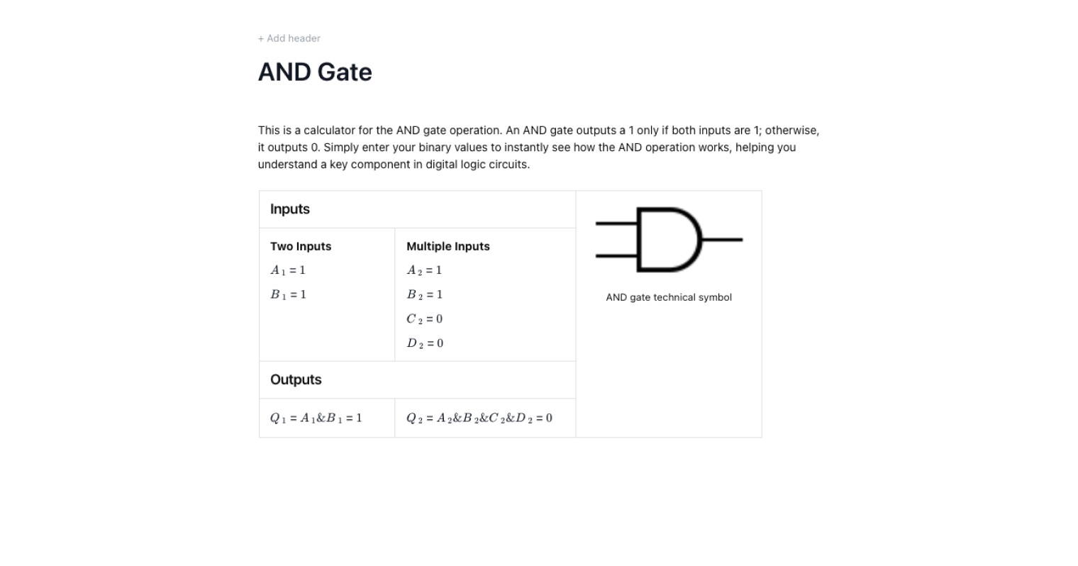
- An and gate only outputs HIGH when all the inputs are HIGH.
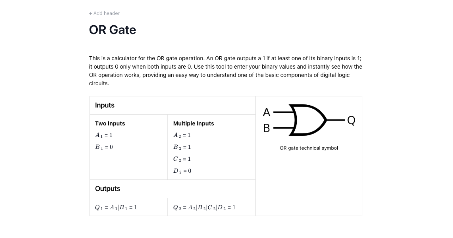
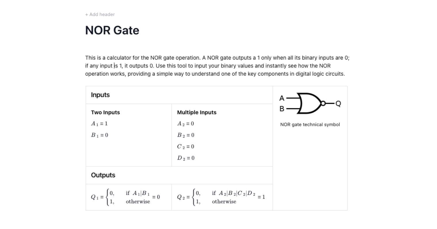
- An or gate gives a HIGH output if at least one input is HIGH.
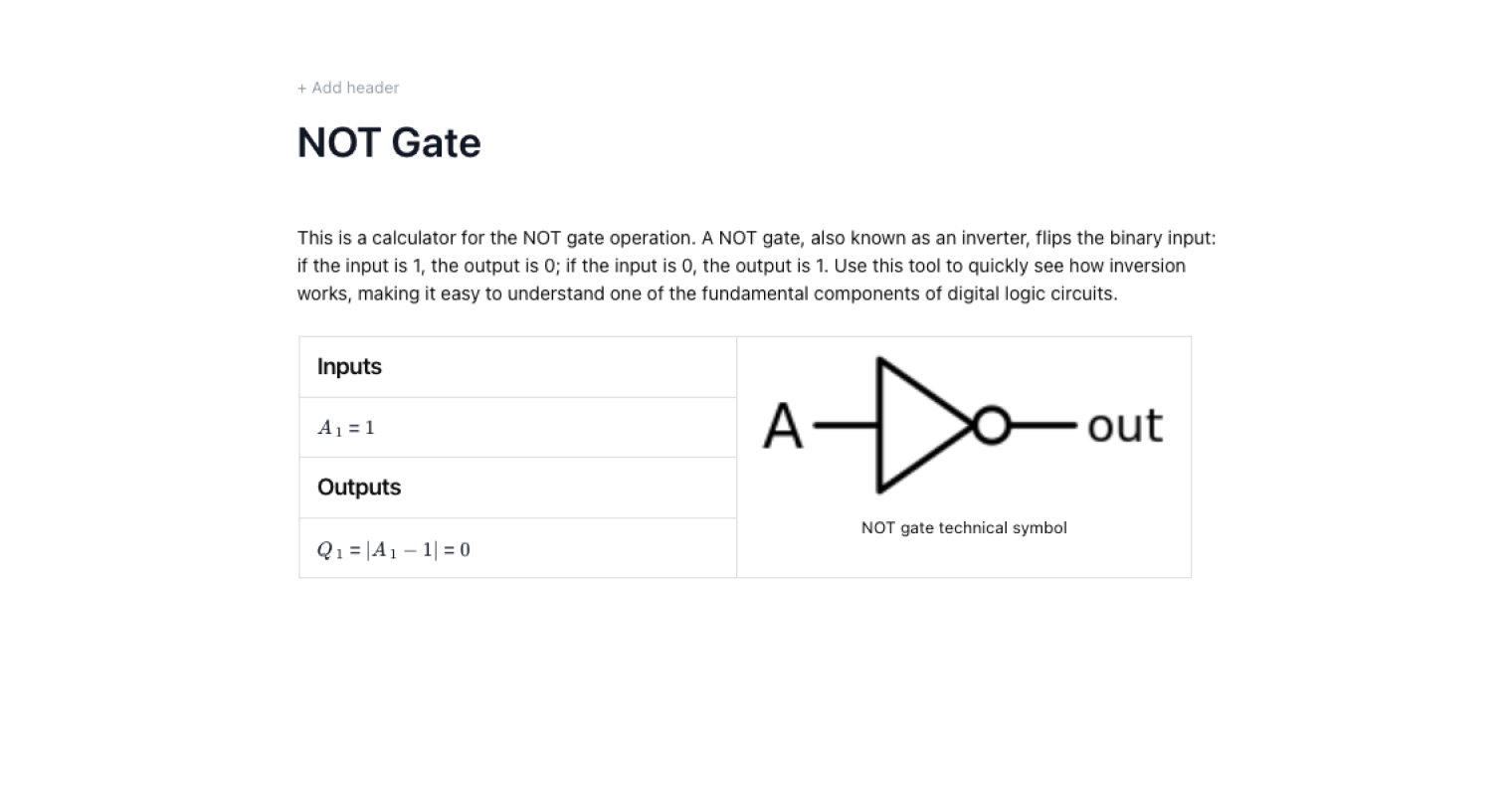
- A not gate, the only single input gate, inverts the input — HIGH becomes LOW and vice versa.
These gates were historically built using vacuum tubes, but now they’re embedded in integrated circuits for efficiency.
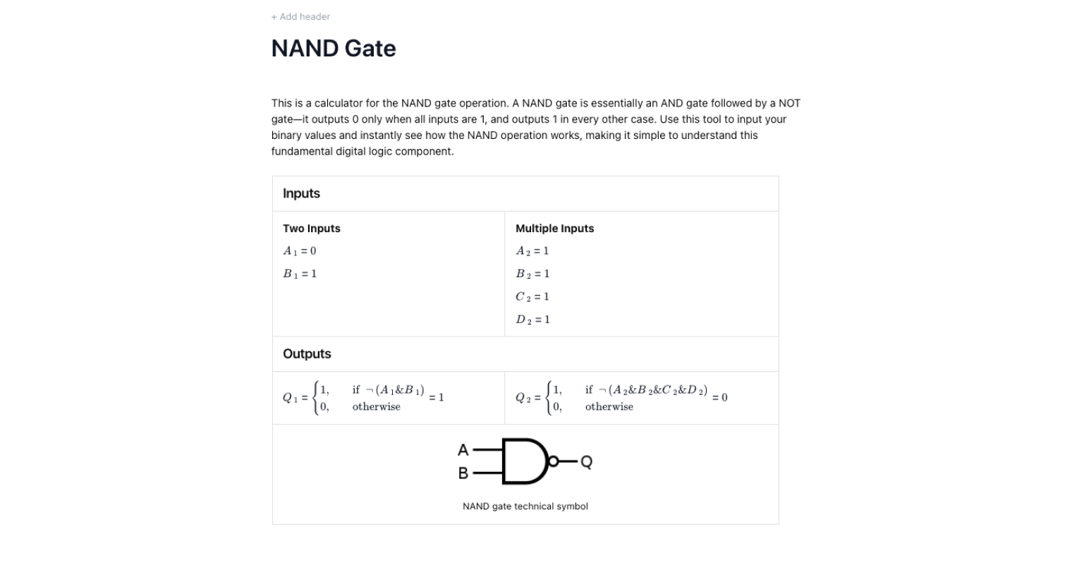
The NAND Gate and Universal Gates
The nand gate — short for NOT-AND — is a cornerstone in digital electronics because it’s a universal logic gate. A nand gate produces a LOW output only when both two inputs are HIGH; otherwise, the output is HIGH. Engineers can create more gates and even replicate all the gates in a system using only nand gates, which is crucial for designing logic circuits efficiently.
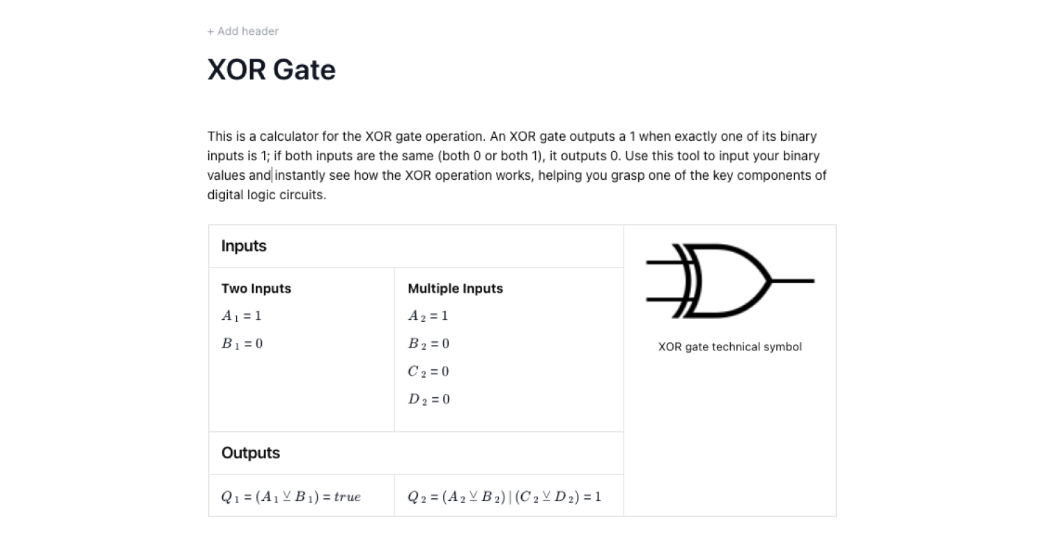
XOR and XNOR Gates for Complex Logic
Moving beyond basic logic gates, xor gates and xnor gates handle more complicated operations in digital circuits.
- xor gates (exclusive OR) return HIGH when the input values differ.
- xnor gates return HIGH when two inputs are the same.
These gates are essential for arithmetic in digital systems, forming the foundation for adders, parity checkers, and memory devices.
Truth Tables and Circuit Diagrams
Each gate can be represented by a truth table, which shows every possible input applied and its corresponding output. For example, an and gate has four combinations of two inputs and a single output in each case. A simulator displays these in the same way they would appear on paper, helping users test circuit diagrams visually before implementation.
Common Calculation Errors to Avoid
When working with a logic gates simulator, engineers often make predictable mistakes:
- Mixing up NOT with NAND: A not gate takes a single input, while a nand gate always requires two inputs — confusing these can lead to the wrong output.
- Incorrect truth table assumptions: Some assume xor gates behave like or gates. They don’t. Always check the truth table.
- Forgetting that most logic gates assume clean HIGH/LOW levels: Any noise in input values can lead to an unexpected low output.
- Assuming one output for every gate works the same across devices: While there is always a single output, hardware tolerances in integrated circuits can vary.
Using a simulator helps reveal these issues before building with real electrical components.
Engineering templates
Common calculators
Design guides
FAQs
What are the most important logic gates to learn first?
Start with and gate, or gate, and not gate. These basic logic gates are the foundation for more gates like xor gates and xnor gates.
Can you design every circuit with only NAND gates?
Yes, because the nand gate is a universal logic gate, you can replicate all the gates using only nand gates.
Why do truth tables matter in digital electronics?
A truth table clarifies exactly how input combinations generate a single output, which is critical for debugging digital circuits.
Are logic gates still built with vacuum tubes?
Historically yes, but today’s digital systems rely on integrated circuits, not vacuum tubes, for compact, efficient designs.
Summary and References
A logic gates simulator lets engineers and students experiment with every gate — from a nand gate to an xnor gate — by toggling input values and instantly seeing the output on a truth table. These tools simplify understanding of digital electronics, circuit diagrams, and the building blocks of modern digital systems.
For further reference, check:
- IEEE Digital Logic Standards
Learn about the benefits of using CalcTree on engineering projects!