
Free flow net example in Python: seepage, uplift and exit gradient under a weir with a sheet pile, checked against Harr. Open a copy in your browser.

Tell us what you need, or sign up and build it yourself in minutes.
Leave your email and we'll tell you when a template for it is ready:




No items found.
No items found.
About this Flow Net Example
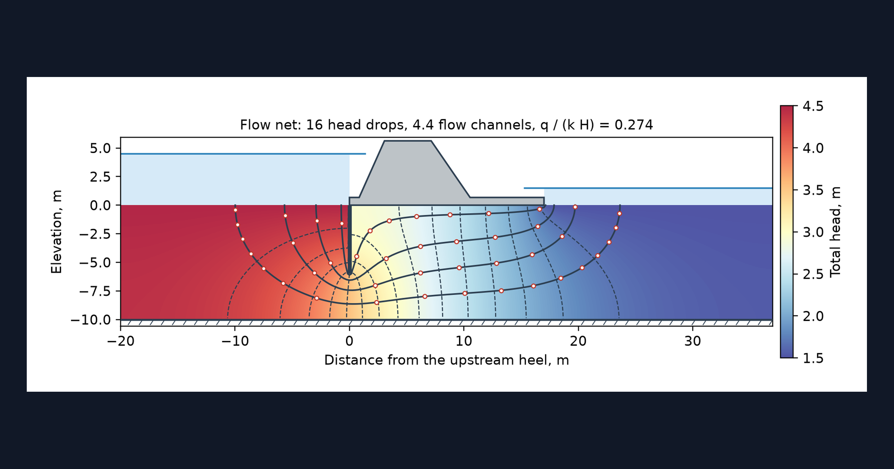
This page is a worked example of a flow net calculation in Python, running in your browser inside a CalcTree calculation page. A finite-volume solver finds the head under a concrete weir with a sheet pile cutoff and draws the equipotentials and flow lines to true scale. From the same solution it works out the seepage, the uplift under the base and the exit gradient, and compares the solver with the published closed-form solution for a sheet pile.
- Geotechnical or civil engineer: see how the position and depth of a cutoff change uplift and exit gradient, and adapt the example to your own section.
- Engineer exploring Python in calculations: see a solver, a true-scale flow net and a closed-form check living in one calculation page.
- Student or graduate engineer: compare a computed flow net with the one you would sketch by hand, and read the solver that draws it.
It is an example of what a CalcTree page can do, built with CalcTree AI, not a design method to rely on as is. The model is idealised and its limits are stated on the page. Duplicate it into your own workspace to change the inputs, read the Python, or use it as the starting point for your own analysis, and verify anything you take into a real design.
More info on Flow Net Calculation
Inputs
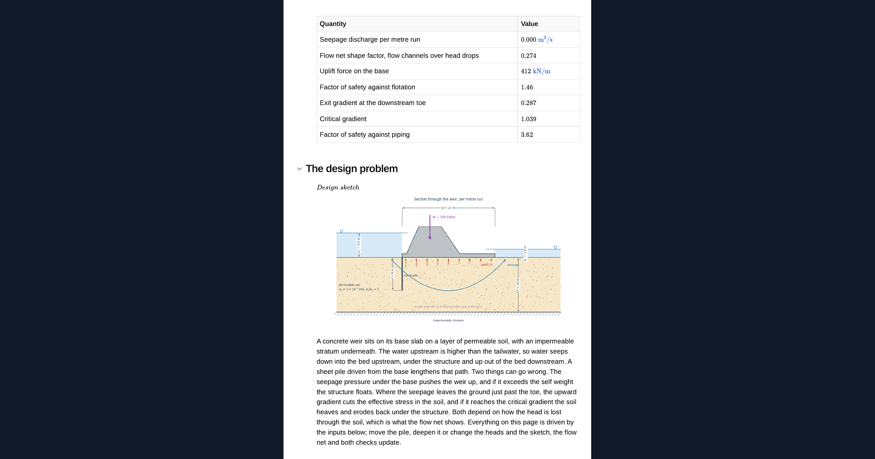
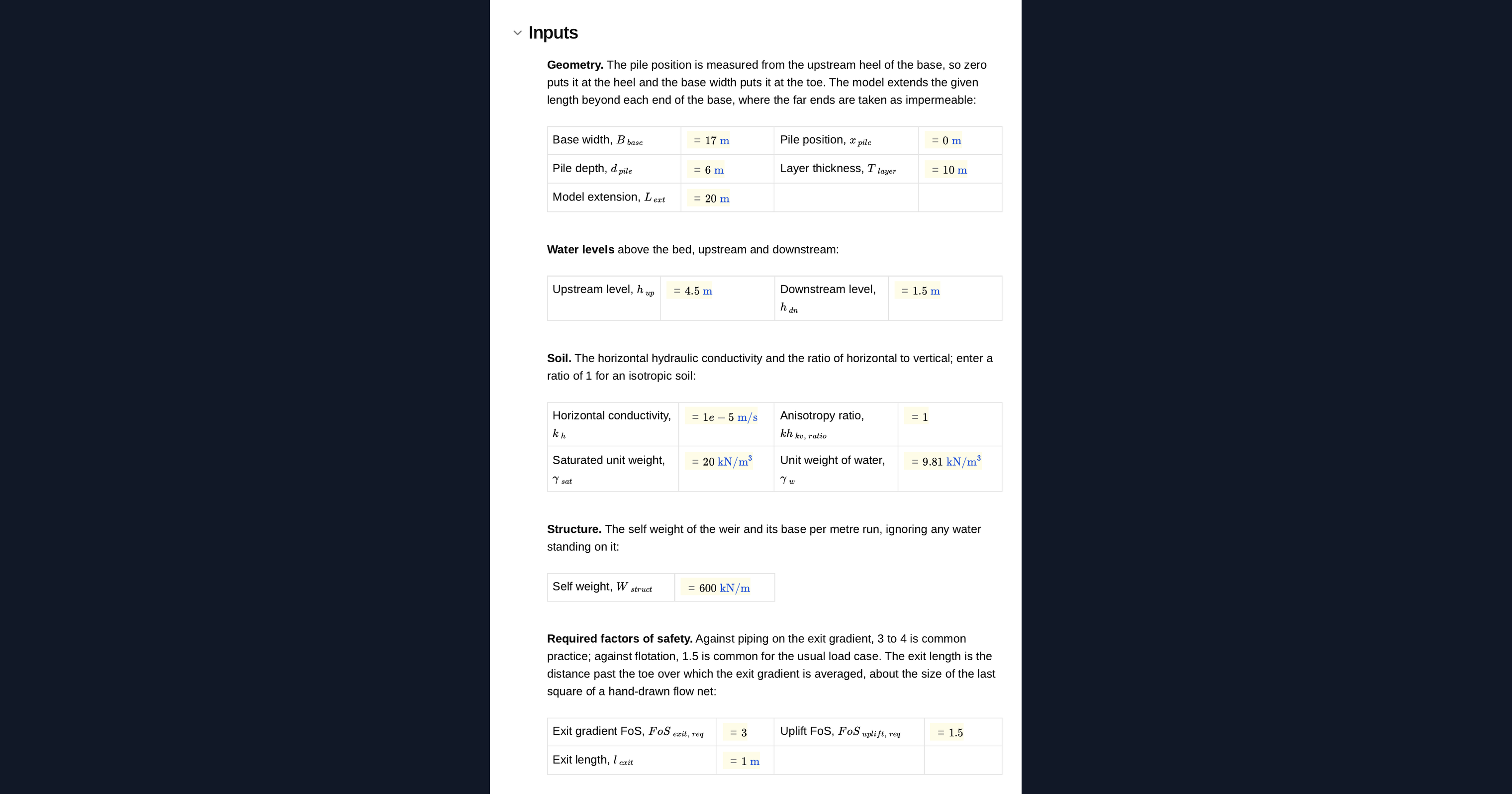
You set the base width of the weir, the position and depth of the sheet pile, the depth of the permeable layer and how far the model extends beyond the structure. The water levels upstream and downstream give the head lost through the soil. The soil is described by its horizontal hydraulic conductivity, the ratio of horizontal to vertical conductivity and its saturated unit weight, and the structure by its self weight per metre run. Required factors of safety, the exit length, the grid and the number of head drops in the flow net are all inputs too. A design sketch of the section redraws from them.
The seepage method
Darcy's law and continuity give Laplace's equation for the total head. The solver splits the layer into square cells, writes one flow balance per cell and solves the whole sparse system at once. The upstream and downstream bed are held at the two water levels, and the base, both faces of the pile, the impermeable stratum and the far ends carry no flow. Flow lines come from a stream function built from the face fluxes, so the flow between any two lines is exact for the solved field. Because flow concentrates at the pile tip and the corners of the base, the discharge and the exit gradient are extrapolated from two grids to zero cell size. Anisotropic soil is handled directly through the face conductances.
Checking the solver
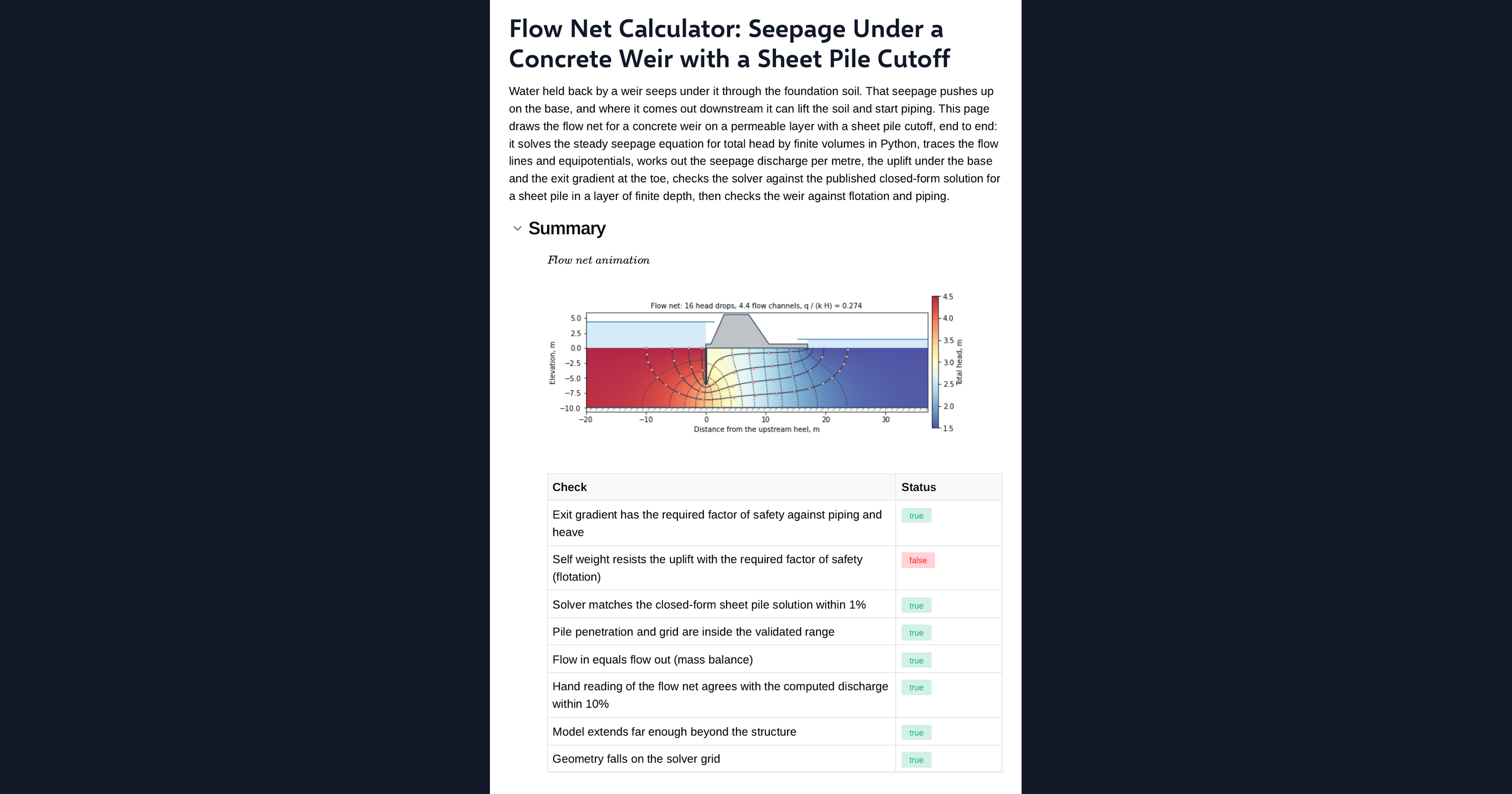
The page runs a second problem alongside the design: a single sheet pile at the same penetration ratio in a layer of the same depth, with no structure. It compares the computed shape factor with Harr's conformal-mapping solution, evaluated on the page through elliptic integrals, and flags whether they agree within tolerance and whether the penetration ratio and grid are inside the validated range. It also checks that the flow in equals the flow out and that a hand count of flow channels gives the computed discharge.
Flotation and piping checks
The uplift is the water pressure under the base from the solved head field, compared with a straight-line creep estimate on a chart. The flotation check compares the self weight with the uplift. The exit gradient is the upward gradient at the bed just past the toe, averaged over the exit length, and the piping check compares it with the critical gradient from the soil's submerged unit weight. The page then tells you what to change if either check fails.
Python libraries used
NumPy builds the grid, the face conductances and the stream function from the face fluxes. SciPy assembles the flow balance as a sparse matrix and solves it in one step. contourpy traces the equipotentials and flow lines from the solved head and stream function. Matplotlib draws the section, the true-scale flow net and the particles moving along the flow lines.
Common Calculation Errors to Avoid
- Reading the exit gradient at the corner: the gradient at the downstream corner of a base is theoretically infinite, so it has to be averaged over a stated exit length, and a shorter length gives a larger value.
- Putting the cutoff in the wrong place for the problem: a pile at the upstream heel cuts uplift, a pile at the toe cuts the exit gradient, and moving one improves one check at the expense of the other.
- Using linear creep for the uplift: sharing the head loss evenly along the seepage path overstates the uplift just past an upstream pile and understates it towards the toe.
- Ignoring anisotropy: a soil that is more permeable horizontally than vertically changes both the discharge and the exit gradient, and the section has to be transformed or the conductivities treated separately.
- Truncating the model too close to the structure: impermeable far ends placed near the weir cut off flow paths and understate the discharge.
- Trusting a coarse grid: the flow is singular at the pile tip and the corners of the base, so a single coarse grid underestimates the discharge and the exit gradient unless the result is extrapolated or the grid refined.
Engineering templates
Common calculators
Design guides



FAQs
What is a flow net?
A flow net is a picture of steady seepage through soil: a family of equipotentials, lines of equal total head, crossed at right angles by flow lines, the paths the water takes. Drawn so each field is a curvilinear square, every flow channel carries the same flow and every pair of equipotentials marks the same head drop, so the discharge, the pore pressure at any point and the exit gradient can all be read off it.
Can I do seepage analysis without SEEP/W or PLAXIS?
For a problem like this one, yes. Steady, confined seepage under a structure in a single homogeneous layer is a Laplace problem that a short finite-volume solver handles in seconds, and this page checks its answer against a closed-form solution. SEEP/W, the rest of GeoStudio and PLAXIS cover what this page does not: unconfined flow with a free surface, transient seepage, layered and variable soils, three-dimensional problems and coupled deformation. Use them for those.
How is the computed flow net checked?
Against Harr's closed-form solution for a single sheet pile in a permeable layer of finite depth on an impermeable base, at the same penetration ratio as the design. The page also checks mass balance and that a hand count of flow channels gives the computed discharge, and it flags any pile penetration or grid outside the validated range.
Should the sheet pile go at the upstream heel or the downstream toe?
It depends on which check governs. A pile at the upstream heel lengthens the seepage path before the water reaches the base, which lowers the uplift. A pile at the toe forces the flow to rise further from the exit, which cuts the exit gradient but raises the uplift. Move the pile on the page and both checks update, so you can see the trade-off for your own section.
Does the calculator handle anisotropic soil?
Yes, with a single ratio of horizontal to vertical conductivity. The solver treats the two conductivities directly, which gives the same answer as transforming the section, and reports the discharge against the equivalent conductivity. Layered soils are outside its scope.
Can I change the weir and rerun the flow net?
Yes. It is an example to build on: duplicate the page into your workspace, then change the geometry, the water levels, the soil, the grid or the Python itself. The sketch, the flow net, the uplift and exit gradient charts and every check update together.
Learn about the benefits of using CalcTree on engineering projects!