
Wind force on rectangular section elements to EN 1991-1-4 Section 7.6: force coefficient, end effect, slenderness and Eq. 5.3. Open the free template.

Tell us what you need, or sign up and build it yourself in minutes.
Leave your email and we'll tell you when a template for it is ready:
No items found.
No items found.
About this Rectangular Section Wind Force Calculator
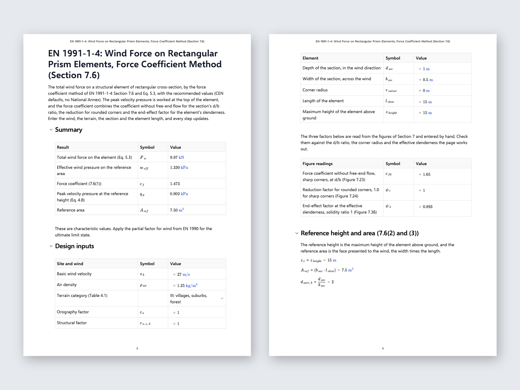
This calculator gives the total wind force on a structural element of rectangular cross-section by the force coefficient method of EN 1991-1-4 Section 7.6 and Eq. 5.3, using the recommended values with no National Annex. The peak velocity pressure is worked at the top of the element, and the force coefficient combines the coefficient without free-end flow for the section's d/b ratio, the reduction for rounded corners and the end-effect factor for the element's slenderness.
- Steel and concrete designer finds the wind force on columns, piers, box sections and isolated members that stand clear of a building envelope.
- Temporary works engineer checks props, towers and rectangular stacks for wind during erection, where the element is exposed on its own.
- Bridge engineer estimates the wind on rectangular piers and pylons for preliminary sizing, with each factor shown against its figure.
The page reports the force, the effective pressure on the reference area, the force coefficient and the peak velocity pressure together. It is an engineering-grade calculation you can duplicate and adapt in a CalcTree workspace.
More info on Rectangular Section Wind Force
Reference height and area
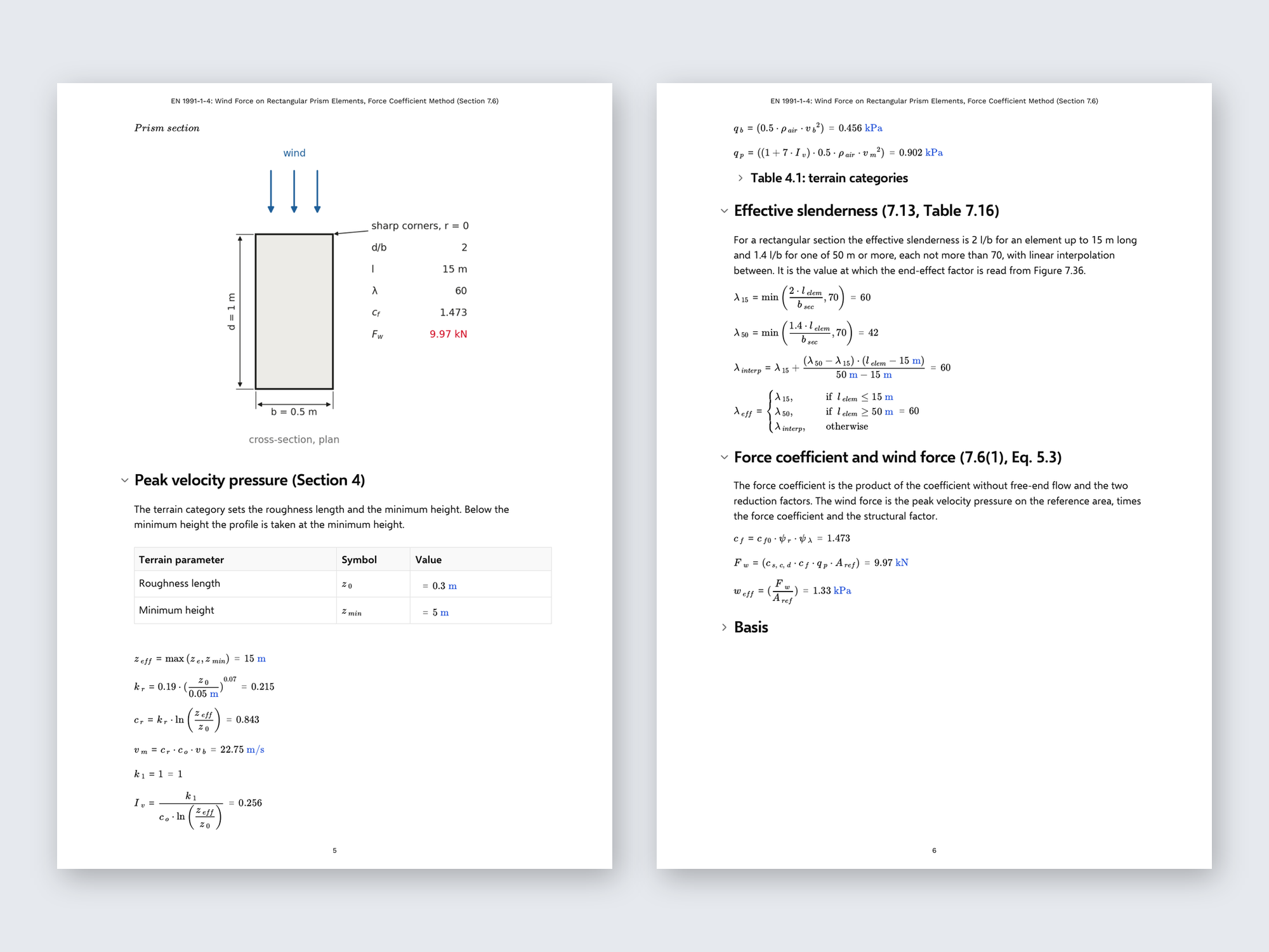
The reference height is the maximum height of the element above ground (7.6(2)), and the reference area is the face presented to the wind, the width times the length (7.6(3)). The peak velocity pressure is worked at the reference height from the basic wind velocity, terrain category and orography factor through Section 4.
Force coefficient readings
The force coefficient is the product of three factors (7.6(1)): the coefficient without free-end flow for sharp corners at the section's d/b ratio (Figure 7.23), the reduction factor for rounded corners (Figure 7.24) and the end-effect factor (Figure 7.36). These are read from the figures and entered by hand, and the page works out the d/b ratio and the effective slenderness to read them against.
Effective slenderness
For a rectangular section, Table 7.16 gives the effective slenderness against the element length and width, each value capped, with linear interpolation between the short and long element cases. The page computes all three values and selects the one for the element length, ready to read the end-effect factor from Figure 7.36 at solidity ratio 1.
Wind force
The total wind force is the structural factor times the force coefficient, the peak velocity pressure and the reference area (Eq. 5.3). The effective wind pressure is that force spread over the reference area, for global design only. Results are characteristic and need the partial factor from EN 1990 for the ultimate limit state.
Common Calculation Errors to Avoid
- Swapping d and b d is the depth in the wind direction and b the width across it. Reversing them reads the wrong point on Figure 7.23 and gives the wrong reference area.
- Not updating the figure readings The three factors are entered by hand. After changing the section, corner radius or length, re-read them against the new d/b ratio and slenderness the page reports.
- Ignoring end effects Using the coefficient without free-end flow alone overstates the force on a short element. The end-effect factor from Figure 7.36 accounts for flow round the free end.
- Taking the structural factor as 1.0 for a sensitive element The default suits most stiff elements. Tall, slender or dynamically sensitive elements need the structural factor from Section 6.
- Using the effective pressure for local design The effective pressure is the total force spread over the reference area. It is not a local pressure for cladding or connections.
Engineering templates
Common calculators
Design guides




FAQs
What is the force coefficient method?
It gives the overall wind force on a structure or element as the product of the structural factor, a force coefficient, the peak velocity pressure and a reference area (Eq. 5.3). It suits isolated members where a single resultant is needed rather than a pressure distribution.
Why are the figure values entered by hand?
Figures 7.23, 7.24 and 7.36 are curves. The page works out the d/b ratio and effective slenderness that locate the reading, and leaves the reading itself to the engineer so it can be checked against the figure.
Where is the reference height taken?
At the maximum height of the element above ground. Below the minimum height for the terrain category the minimum height is used for the wind profile.
Does the page handle rounded corners?
Yes, through the reduction factor from Figure 7.24, read against the ratio of corner radius to width. For sharp corners the factor is 1.0.
Are the results design values?
No. The force and pressure are characteristic values. Apply the partial factor for wind from EN 1990 for the ultimate limit state.
Learn about the benefits of using CalcTree on engineering projects!