
Design a reinforced concrete T-section in bending to Eurocode 2. Get the steel area with every step shown. Try the free calculator.

This template is not available yet. You can sign up and create it yourself!
Or let us know if you'd like to be notified when it’s ready:
No items found.
No items found.
About this EC2 Bending Design of a T-Section Calculator
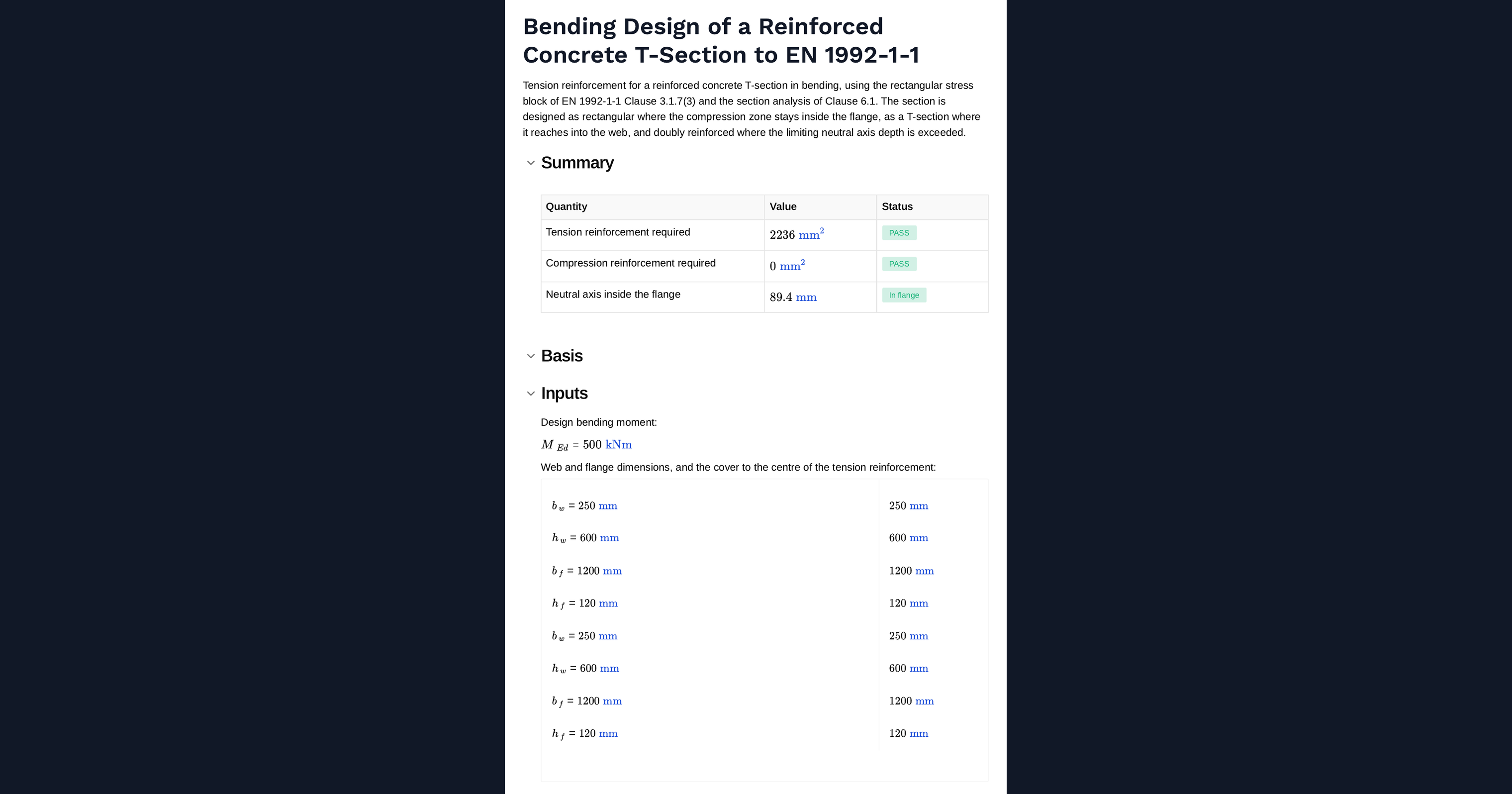
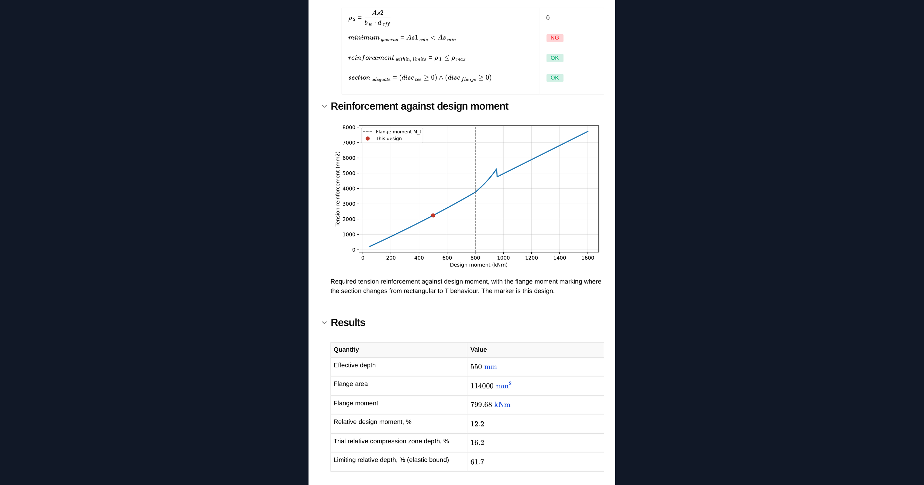
This calculator designs the tension reinforcement for a reinforced concrete T-section in bending, using the rectangular stress block of EN 1992-1-1 Clause 3.1.7 and the section analysis of Clause 6.1. It works out whether the compression zone stays within the flange or reaches into the web, designs the section accordingly, and adds compression reinforcement where the limiting neutral axis depth is exceeded. A chart plots the reinforcement required across a range of design moment, with the flange moment marked.
- Structural engineer. Enter the web and flange dimensions, materials and design moment, and read the tension steel required with the governing behaviour identified.
- Design reviewer. See whether the neutral axis fell inside the flange and whether the section went singly or doubly reinforced, which is where T-section design most often goes wrong.
- Engineer sizing a floor. Read off the chart where the section changes from rectangular to T behaviour and how quickly the steel demand rises beyond it.
Every expression is shown with the clause behind it and units are carried through the calculation. It is an engineering-grade calculator you can audit, adapt and save to a project page in CalcTree.
More info on EC2 Bending Design of a T-Section
Inputs
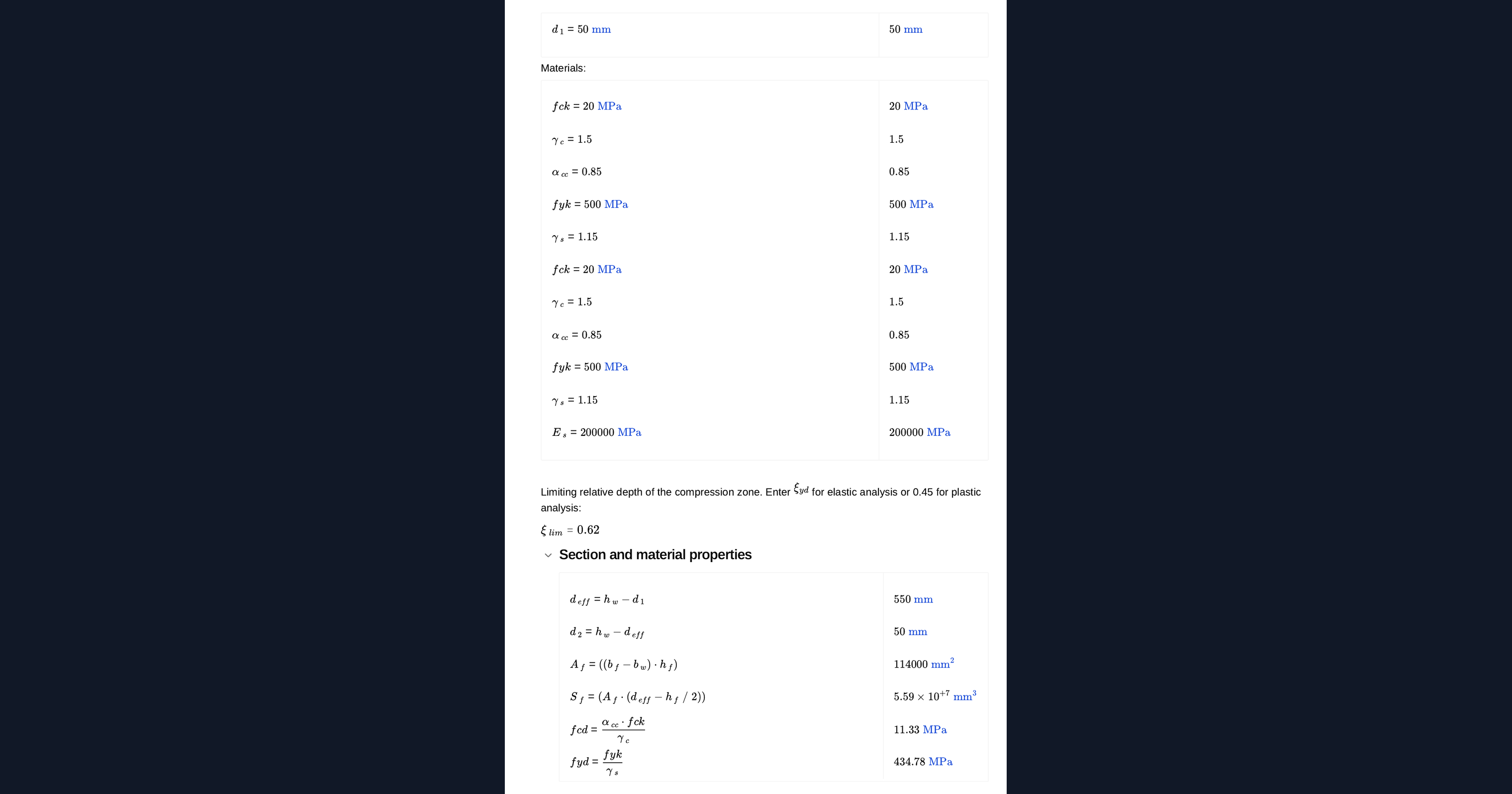
Web width and depth, flange width and thickness, the cover to the centre of the tension reinforcement, the concrete and steel grades, the design bending moment, and the limiting relative depth of the compression zone.
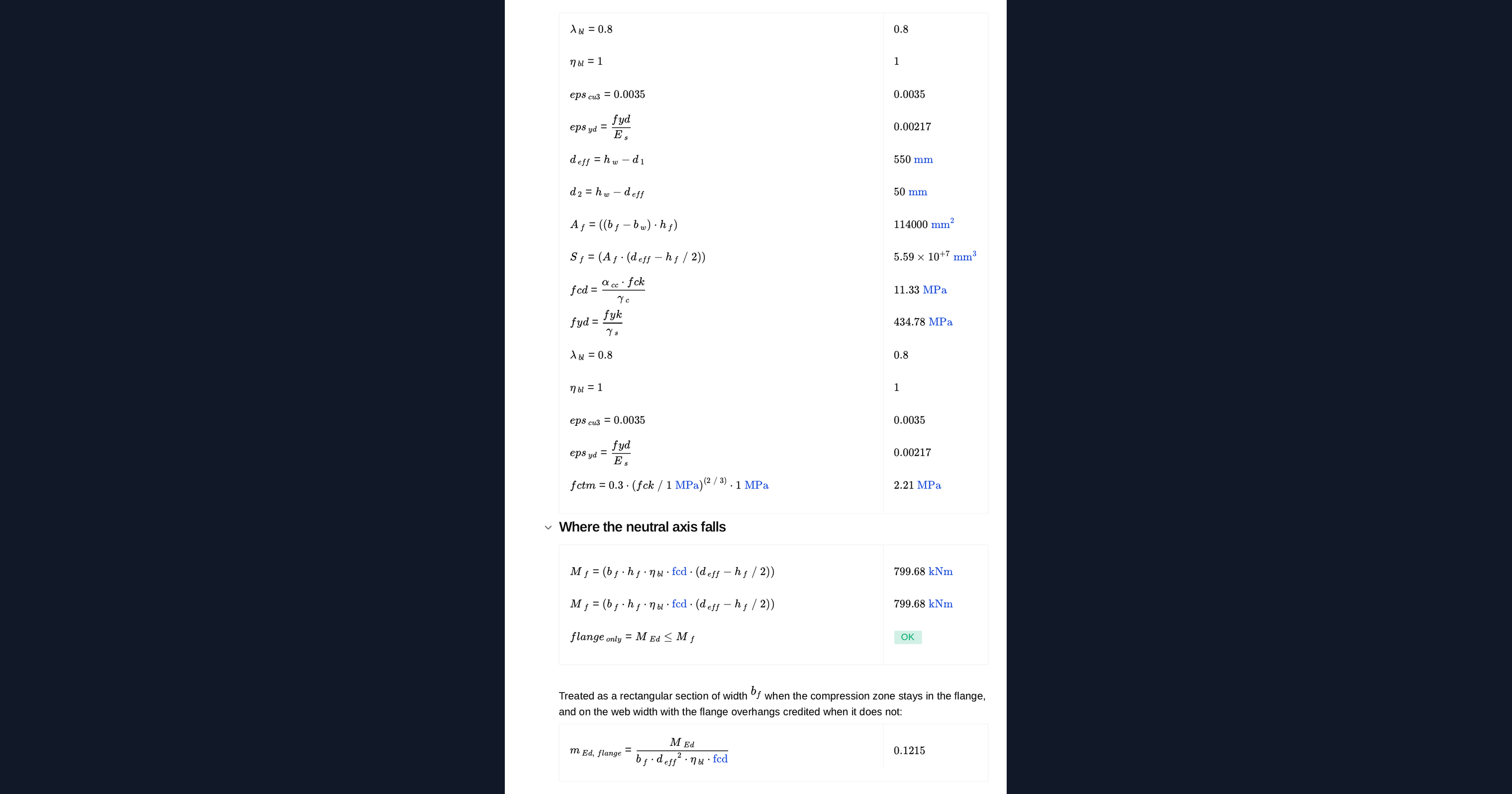
Where the neutral axis falls
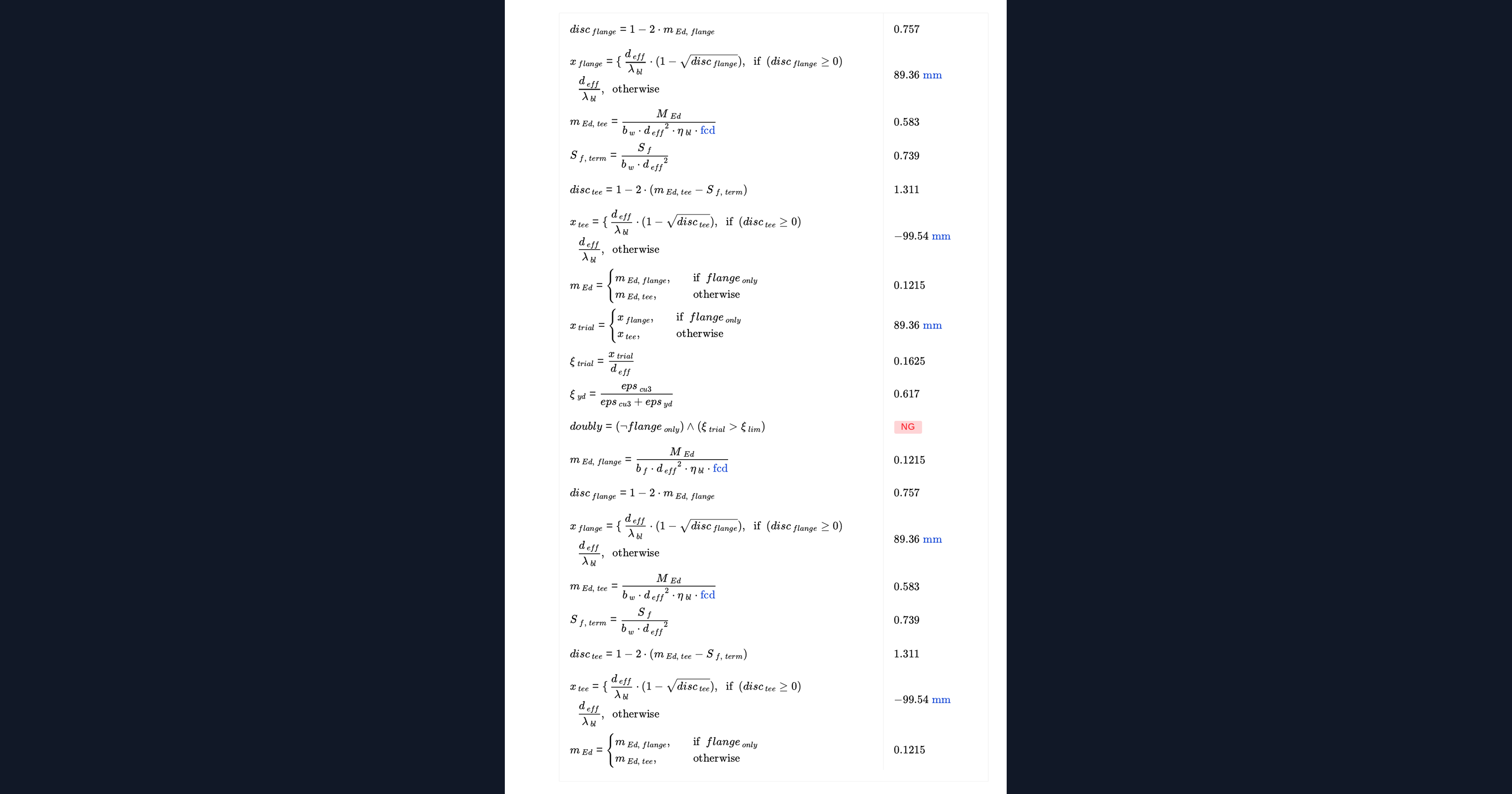
The moment that puts the compression zone exactly at the underside of the flange separates two behaviours. Below it the whole compression zone is in the flange and the section behaves as a rectangular one of the full flange width. Above it the zone extends into the web and the flange overhangs are credited through their first moment of area.
Singly and doubly reinforced
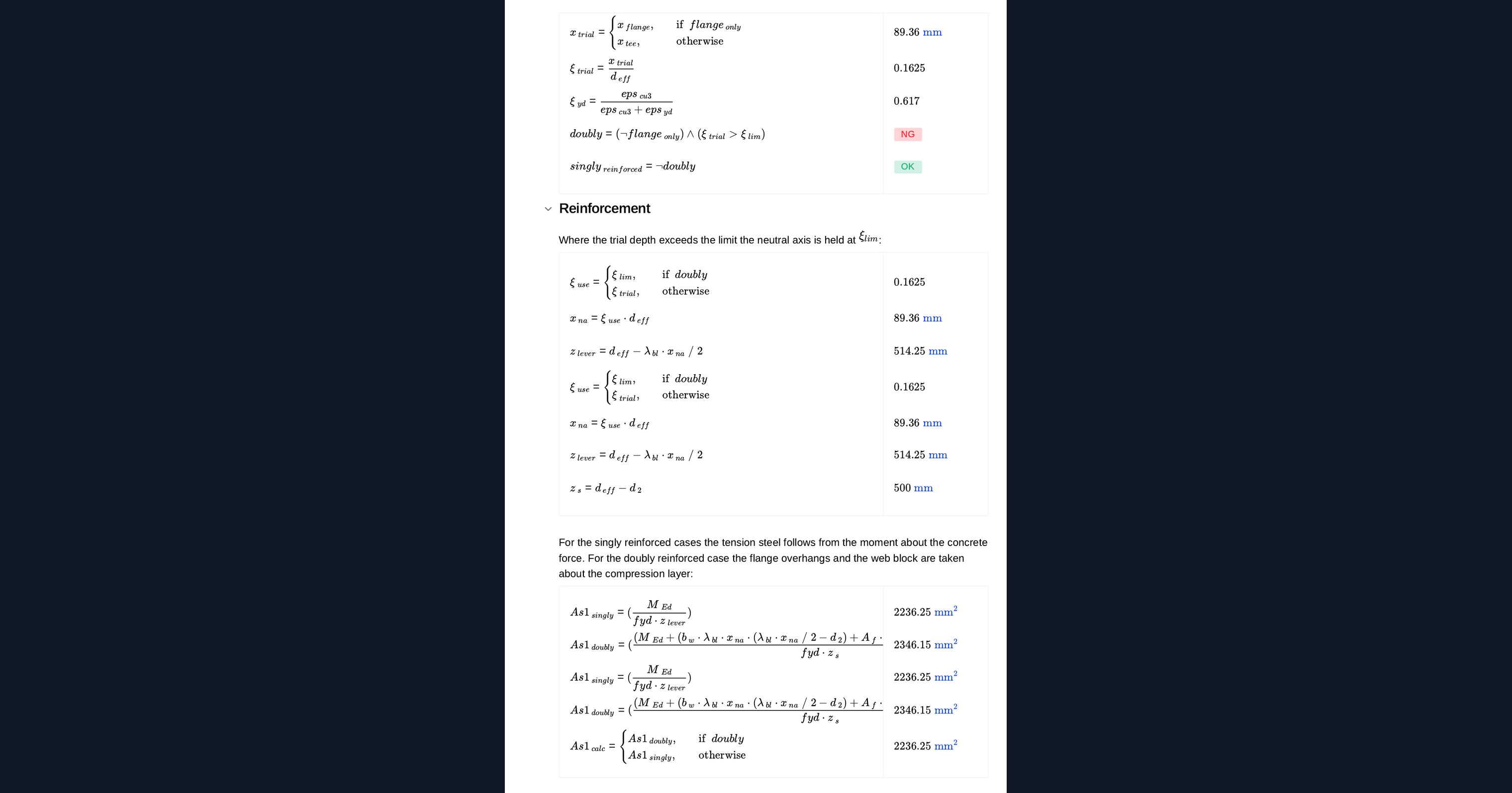
The relative depth of the compression zone is compared with a limiting value that reflects the ductility required. Where it is exceeded, the neutral axis is held at the limit and compression reinforcement carries the surplus, with its stress limited to the strain-compatible value.
Outputs
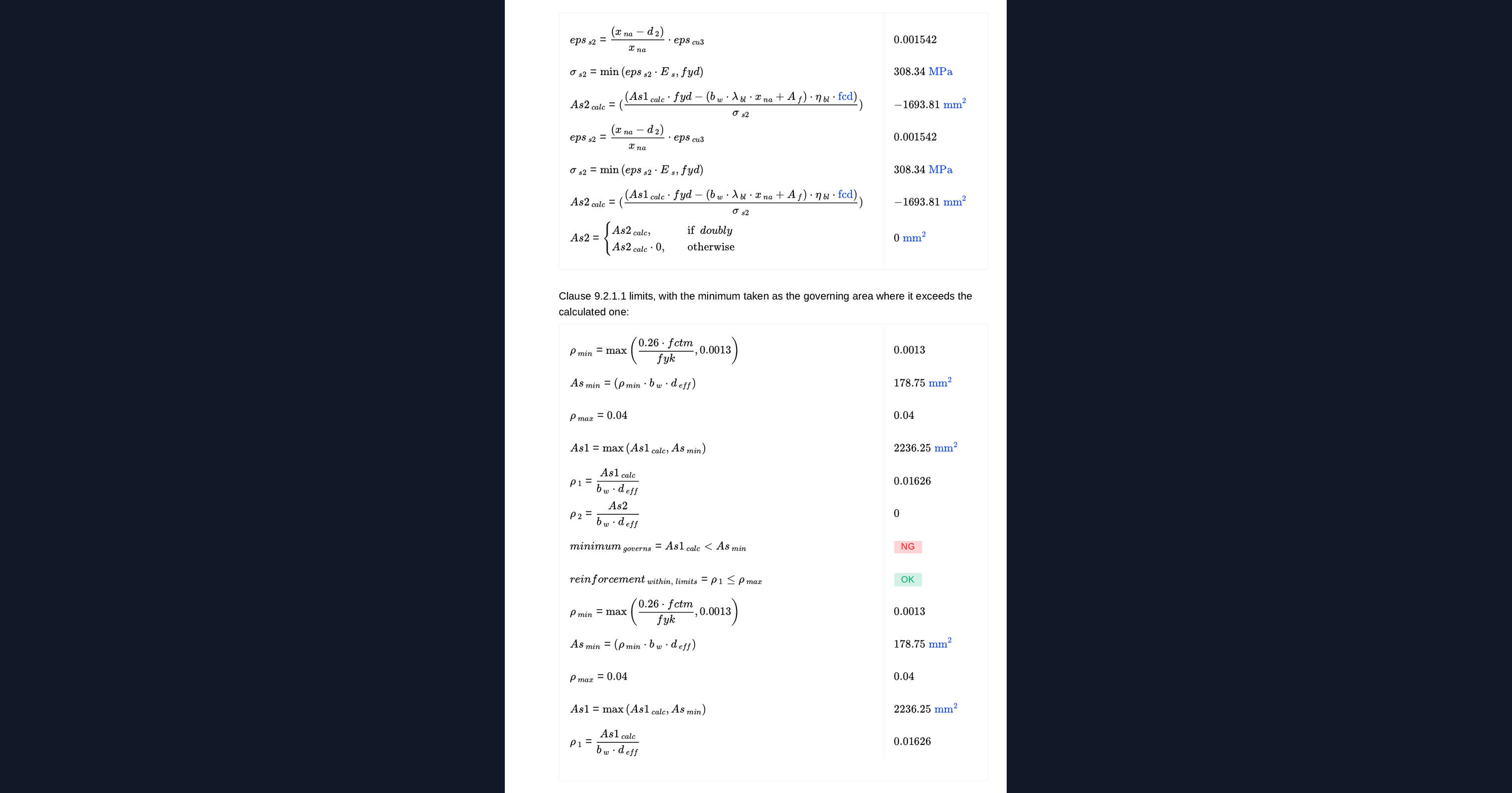
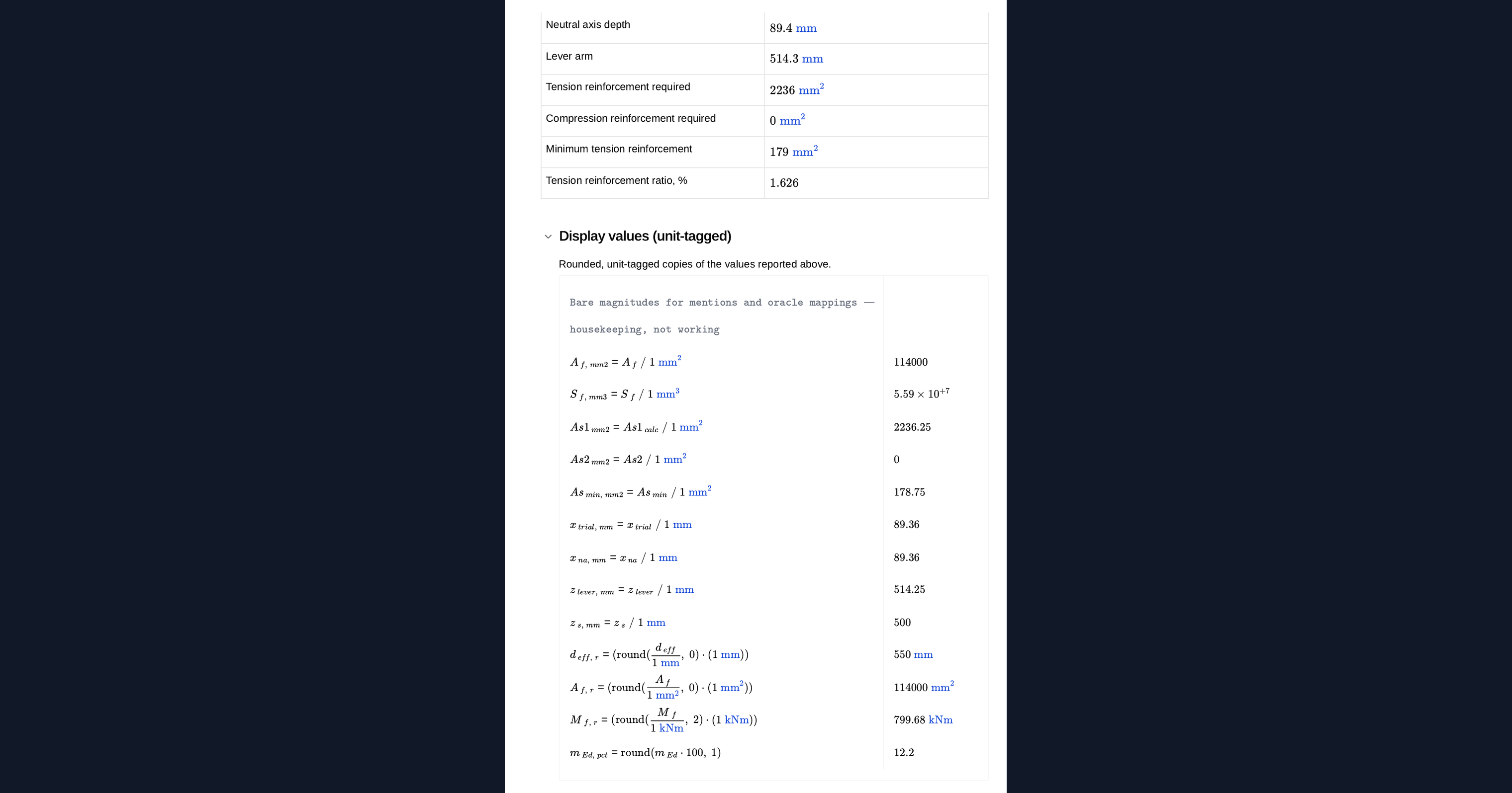
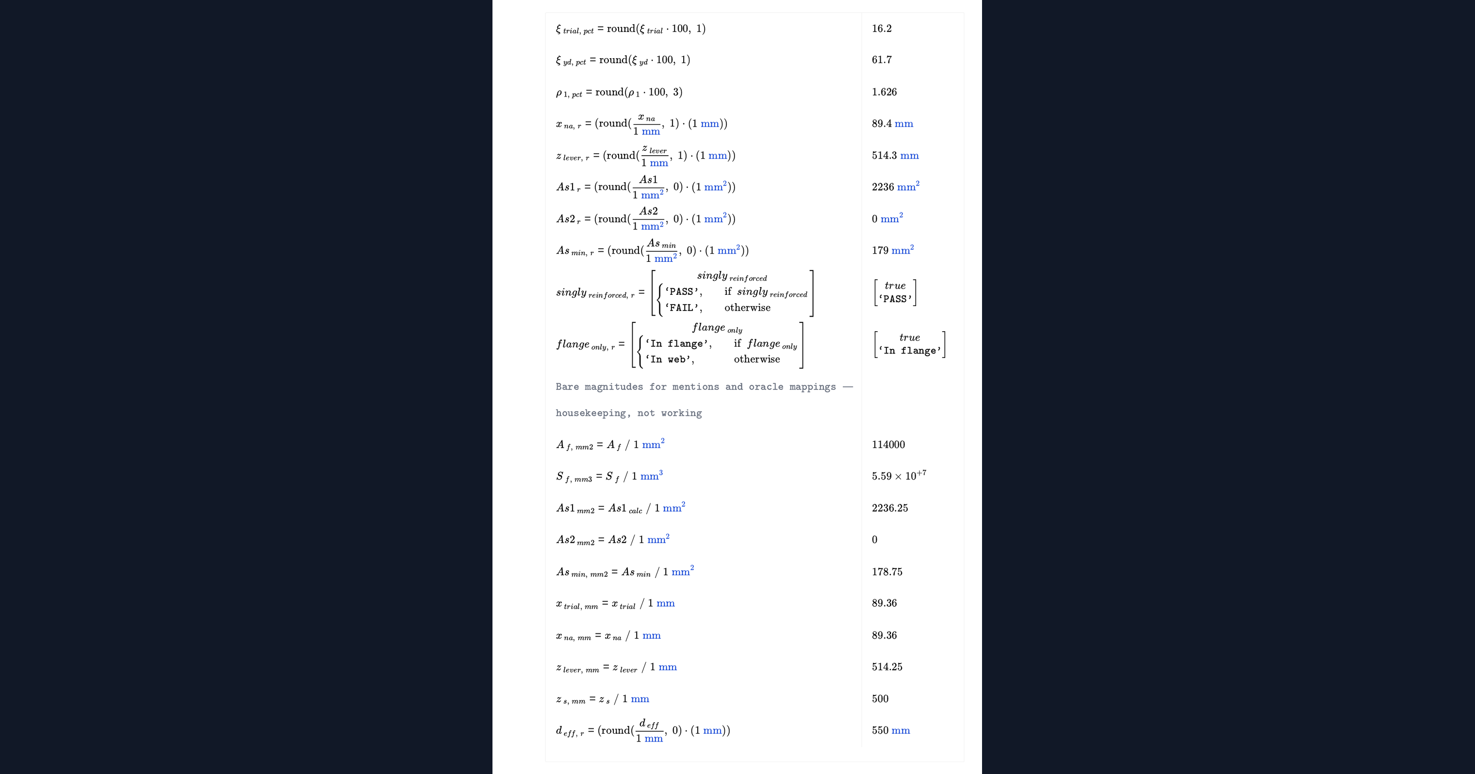
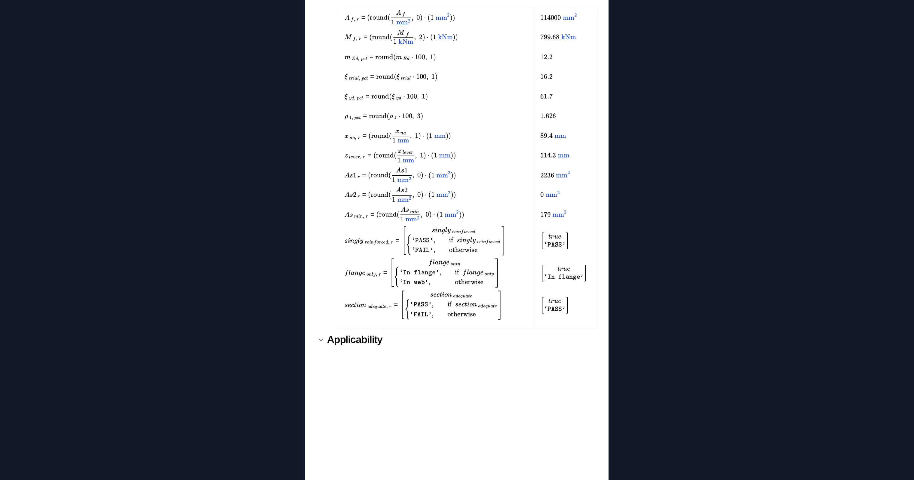
The neutral axis depth, the lever arm, the tension reinforcement required and the compression reinforcement where the section needs it, together with the minimum and maximum reinforcement limits of Clause 9.2.1.1.
Common Calculation Errors to Avoid
- Using the full physical flange width. The effective flange width must be established separately from the span and the web spacing, and entering the physical width overstates the compression capacity.
- Assuming the flange is always in compression. Where the flange is in tension the section is designed as rectangular on the web width, which is a different calculation.
- Designing on the web width when the neutral axis is in the flange. That understates the compression zone available and gives more steel than the section needs.
- Ignoring the ductility limit. The limiting relative depth is a design choice, and a section allowed to run deeper than intended may not be ductile enough for the analysis assumed.
- Forgetting the minimum reinforcement. A lightly loaded section can need more steel than the bending calculation gives, and the minimum then governs.
- Treating this as a complete design. Shear, deflection and crack width are separate checks and any of them can control the final section.
Engineering templates
Common calculators
Design guides




FAQs
When does a T-section behave as a rectangular one?
Whenever the compression zone stays within the flange thickness. Below the moment that puts the neutral axis at the underside of the flange, the section is designed as a rectangle of the full effective flange width.
What effective flange width should I use?
Not the full physical width. It must be established from the span and the spacing of the webs under a separate clause, and entering the physical width will overstate the capacity.
When is compression reinforcement needed?
When the relative depth of the compression zone exceeds the limit set for the ductility assumed. The neutral axis is then held at that limit and compression steel carries the moment above what the concrete alone can take.
What limiting relative depth should I enter?
It is a ductility choice. A value around the elastic bound suits elastic analysis, and a lower value is usual for plastic analysis with no redistribution. The calculator reports the elastic bound for reference.
Does this cover axial force?
No. This is pure bending. A section carrying axial load as well needs an interaction analysis, which is a different calculation.
Learn about the benefits of using CalcTree on engineering projects!