Free Duct Pressure Drop Calculator. Step-by-step, engineering-grade tool with downloadable report.

This template is not available yet. You can sign up and create it yourself!
Or let us know if you'd like to be notified when it’s ready:
No items found.
No items found.
About this 'Duct Pressure Drop Calculator'
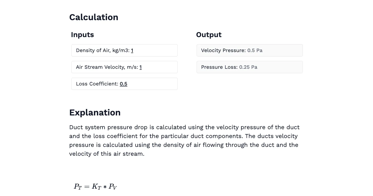
The Duct Pressure Drop Calculator is designed to estimate pressure loss in ventilation ductwork by calculating air velocity and pressure drop based on user-defined parameters. By entering values such as duct diameter, duct length (in feet, inches, or metric units), and airflow rate (typically in CFM), users can quickly determine pressure losses caused by friction and velocity. The calculator applies established fluid mechanics formulas to provide engineers with accurate and actionable results for use in HVAC system design and optimization.
This calculator is for:
- HVAC Engineers: Optimize ductwork designs by accurately estimating pressure drops to improve energy efficiency and system performance.
- Building Designers: Ensure proper ventilation and air distribution in buildings by understanding duct pressure requirements.
- Mechanical Engineering Students: Gain hands-on experience with fluid mechanics concepts applied to real-world HVAC scenarios.
With the Duct Pressure Drop Calculator, you can perform quick feasibility checks for duct sizing and airflow optimization. Users receive immediate outputs including air velocity, pressure drop, and friction loss, based on the duct shape—whether round or rectangular. The calculator uses a series of equations, including those for friction loss and to calculate air velocity.
For example, you might enter a flow rate of 1200\(cfm\) and a duct length of 100\(ft\) to calculate the pressure drop for a 100\(ft\) round duct.
For more complex scenarios involving multiple branches or variable airflows, advanced tools like Computational Fluid Dynamics (CFD) software can provide detailed analyses. For theoretical knowledge, refer to textbooks such as ASHRAE Handbook: Fundamentals or Mechanical and Electrical Equipment for Buildings by Walter T. Grondzik and Alison G. Kwok.
Note: The calculator supports both imperial and metric units, and exact values for flow rate, air flow volumes, and duct dimensions can be entered for precise calculations.
Introduction to Duct Systems
Duct systems form the backbone of modern heating, ventilation, and air conditioning (HVAC) systems, ensuring that air is efficiently distributed throughout buildings for optimal comfort and indoor air quality. The design and sizing of ducts are critical, as they directly affect air velocity, duct length, and pressure drop within the system. HVAC professionals rely on established methods such as the velocity reduction method and the equal friction method to determine the most effective duct size and layout for each unique building.
When planning duct systems, several factors must be considered, including the desired airflow, the total length of the duct runs, and the acceptable levels of noise and pressure drops. Properly sized ducts help maintain efficient air movement, reduce energy consumption, and minimize operational noise, all of which contribute to a more comfortable and cost-effective environment. Careful consideration of these parameters during the design phase enables engineers to deliver systems that are cost-effective, quiet, and thermally efficient.
Hydraulic Diameter and Its Applications
Hydraulic diameter is a key concept in the design and analysis of duct systems. In systems with non-circular ducts, such as rectangular ductwork, the hydraulic diameter is used to equate airflow characteristics with those of a circular duct. The hydraulic diameter is calculated using the formula:
$$D_h= \frac{4 \times \text{Area}}{\text{Perimeter}}$$
Where \(Dh\) represents the hydraulic diameter, and the area and perimeter refer to the cross-sectional dimensions of the duct.
This allows engineers to apply standard fluid flow equations even when duct shapes vary. The hydraulic diameter plays a critical role in determining the Reynolds number and friction factor, both of which influence pressure drop and airflow behavior. These calculations help engineers make informed decisions when selecting duct sizes and materials, ensuring that ventilation systems operate efficiently with minimal energy loss. Understanding how to apply hydraulic diameter ensures accurate modeling of airflow in both new construction and retrofit projects.
Engineering templates
Common calculators
Design guides
FAQs
What factors influence pressure drop in HVAC ducts?
Key factors include friction loss, duct size, shape, length, airflow velocity, air density, and the number of fittings or bends in the duct system.
How can pressure drop be minimized in duct design?
Using larger duct sizes, smoother duct surfaces, and minimizing sharp bends or sudden changes in duct dimensions can reduce pressure drop.
What is the difference between velocity pressure and static pressure?
Velocity pressure is the pressure due to the motion of air, while static pressure is the pressure exerted by air at rest within the duct.
Learn about the benefits of using CalcTree on engineering projects!