
Determine the moment of inertia across common cross-sections.
Introduction to Moment of Inertia
The moment of inertia, often referred to as the second moment of area, is a fundamental geometrical property in structural engineering that measures how "stiff" a cross-sectional shape is. In other words, it is a measure of a cross-section's resistance to bending and deflection. The second moment of area or moment of inertia is typically denoted by \(I\), and its unit of dimension is a unit value of length to the fourth power,
i.e. \( mm^4 \), \( m^4 \), \( in^4 \).
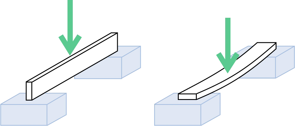
To visualise this property, suppose you are using a rectangular plank of wood to cross a void. You can lay it flat, as shown on the right of the adjacent image, or you can rotate it vertically onto its side, as shown on the left.
Intuitively, the plank on the left will bend less when you stand on it, even though both planks have the same cross-sectional area and material properties. By rotating the plank onto its side, its geometry in relation to the axis of bending changes, and therefore significantly affecting the moment of inertia.
Common Cross-sections
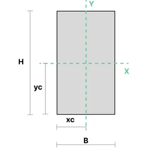
1. Solid Rectangular Section
The moment of inertia of a solid rectangular section can be calculated using the equations below. \(B\) represents the section's width, and \(H\) is its height.
$$
\begin{align}
&I_{xx} = \frac{BH^3}{12} \\\ \\
&I_{yy} = \frac{B^3H}{12}
\end{align}
$$
2. Rectangular Hollow Section (SHS/RHS)
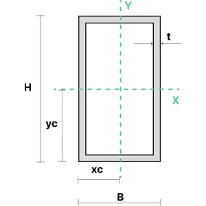
The moment of inertia of a rectangular hollow section can be calculated using the equations shown below. \(t\) is the thickness of the section. \(b\) and \(h\) denote the inner dimensions of the section, and are used to calculate the dimensions of the hollow space.
$$
\begin{align}
&I_{xx} = \frac{BH^3}{12} - \frac{bh^3}{12} \\\ \\
&I_{yy} = \frac{B^3H}{12} -\frac{b^3h}{12} \\\ \\
&b=B-2t \\
&h=H-2t
\end{align}
$$
3. Solid Circular Section
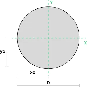
The moment of inertia of a solid circular section can be calculated using the equations shown below. \(D \) represents the section's diameter.
$$
\begin{align}
I_{xx} = \frac{\pi}{64}D^4 \\\ \\
I_{yy} = \frac{\pi}{64}D^4
\end{align}
$$
4. Circular Hollow Section
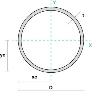
The moment of inertia of a circular hollow section can be calculated using the area moment of inertia formula below. Here, \(d\) is the diameter of the hollow space, and the inner radius r is used to determine the moment of inertia by subtracting the inner circle's inertia (based on r) from the outer circle's inertia.
$$
\begin{align}
&I_{xx} = \frac{\pi}{64}D^4 - \frac{\pi}{64}d^4\\\ \\
&I_{yy} = \frac{\pi}{64}D^4 - \frac{\pi}{64}d^4
\end{align}
$$
5. I Beam
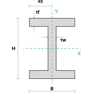
The moment of inertia of an I-section can be calculated using the equations shown below. \(t_w\) is the thickness of the web and \(t_f\) is the thickness of the flanges.
$$
\begin{align}
&I_{xx} = \frac{BH^3-(B-t_{w})(H-2t_{f})^3}{12} \\\ \\
&I_{yy} = \frac{2t_{f}B^3+(H-2t_{f})t_{w}^3}{12}
\end{align}
$$
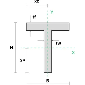
6. T Section
The moment of inertia of an T-section can be calculated using the equations shown below. \(A\) represents the area of the section component, \(t_w\) is the thickness of the web and \(t_f\) is the thickness of the flanges.
$$
\begin{align}
&I_{xx} = \frac{t_{w}H^3+(B-t_{w})t_{f}^3}{3}-A(H-y_{c})^2 \\\ \\
&I_{yy} = \frac{t_{f}B^3+(H-t_{f})t_{w}^3}{12}
\end{align}
$$
7. Angle Section
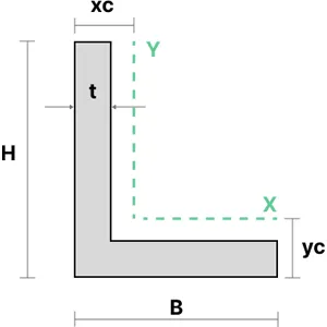
The moment of inertia of an angle section can be calculated using the equations shown below.
\(I_{yy0}\) and \(I_{xx0}\) are the moments of inertia of the section about its base. The parallel axis theorem is applied to this value to determine the moments of inertia about the section centroid, \(I_{yy}\) and \(I_{xx}\).
$$
\begin{align}
&I_{xx_{0}} = \frac{t(H^3+Bt^2-t^3)}{3} \\\ \\
&I_{yy_{0}} = \frac{t(B^3+Ht^2-t^3)}{3} \\\ \\
&I_{xx} = I_{xx_{0}} - Ay_{c}^2 \\\ \\
&I_{yy} = I_{yy_{0}} - Ay_{c}^2
\end{align}
$$
8. Channel Section
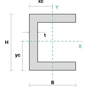
The moment of inertia of an equal channel section can be calculated using the equations shown below. \(x_c\) represents the distance from the centroid of the section from the bottom left-hand corner of the section in the \(x\) direction.
$$
\begin{align}
&I_{xx} = \frac{BH^3-(B-t)(H-2t)^3}{12} \\\ \\
&I_{yy} = \frac{2tB^3+(H-2t)t^3}{3} - Ax_{c}^2
\end{align}
$$
9. Triangular Section
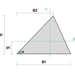
The moment of inertia of a triangular section can be calculated using the equations shown to the right. \(B_1\) represents the section's width, and \(B_2\) represents the horizontal distance between the section's top and bottom left corner.
The centroid of a triangle can be found by averaging the coordinates of its three points.
$$
\begin{align}
&I_{xx} = \frac{B_{1}H^3}{36} \\\ \\
&I_{yy} = \frac{B_{1}H(B_{1}^2-B_{1}B_{2}+B_{2}^2)}{36}
\end{align}
$$
10. Trapezoidal Area Section
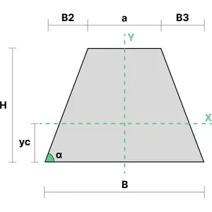
The moment of inertia of a trapezoidal section can be calculated using the equations shown below. \(a\) and \(B\) are the base widths of the section, and \(B_2\) and\(B_3\) are the horizontal distances between the bases.
\(I_{yy0}\) is the moment of inertia of the section about its base. The parallel axis theorem is applied to this value to determine the moment of inertia about the section centroid, \(I_{yy}\).
$$
\begin{align}
&I_{xx} = \frac{H^3}{36} \frac{a^2+4aB+B^2}{a+B} \\\ \\
&I_{yy} = I_{yy_{0}} - Ax_{c}^2 \\\ \\
&I_{yy_{0}} = H\frac{12B^3-3B_{2}^3-B_{3}^3-2B_{3}(3B-B_{3})^2}{36}
\end{align}
$$
Parallel Axis Theorem
The parallel axis theorem involves relating the moment of inertia of a cross-section about an arbitrary reference axis to its moment of inertia about a parallel centroidal axis. This calculation specifically considers two parallel axes: the centroidal axis and another axis offset from it. By knowing the centroidal moment of inertia of a shape, we can easily find its moment of inertia about any other parallel axis using the parallel axes theorem.
The parallel axis theorem is as follows:
$$ I_{total}=I_i+A_i\times {d_i}^2 $$
Where:
\( \rlap{I_i}\hspace{2.5em} \): second moment of area about the centroid of a segment of the cross-section
\( \rlap{A_i}\hspace{2.5em} \): area of a segment of the cross-section
\( \rlap{d_i}\hspace{2.5em} \): distance from the segment centroid to the parallel axis under consideration
The additional term, \(A_i×d_i^2\), is the product of the area and the square of the distance between the two parallel axes.
This theorem is useful for finding the moment of inertia of a complex shape when the axis does not pass through the centroid. The process of finding the total moment of inertia involves summing the centroidal moments and the parallel axis terms for each segment. The moment of inertia is found by applying the formula above for each segment.
Remember to apply the parallel axis theorem whenever you need to find the moment of inertia about an axis that is not through the centroid.
The moment of inertia of the entire cross-section about its centroid is equivalent to the sum of the moments of inertia of each segment about its own centroidal axis and the parallel axis terms.
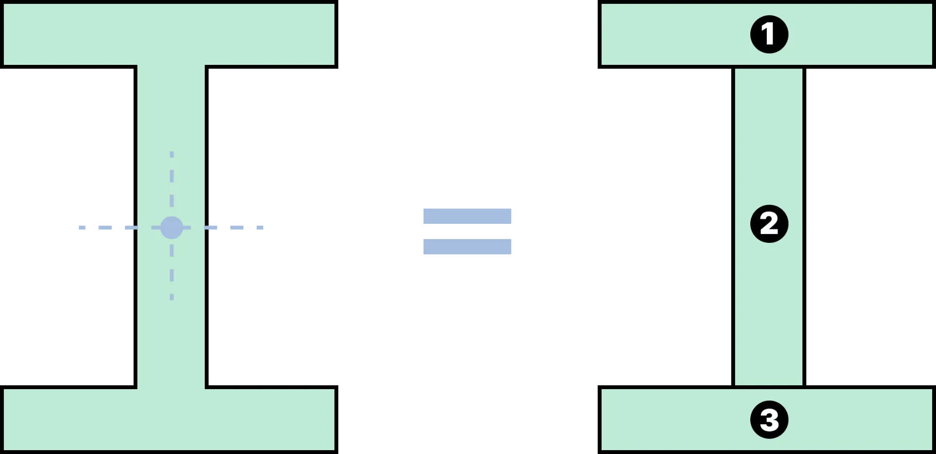
If there are any holes or voids within the cross sections, their moment of inertia must also be calculated but subtracted from the total.
Key Applications
1. Bending Moment of a Beam to its Curvature
When a bending force is applied, the amount the beam bends is proportional to its moment of inertia. A common formula for the bending moment is
$$ M=EIk $$
where \(E\) is the Young's modulus, a property of the material, and \( k \) is the curvature of the beam due to the applied load. \(k\) is determined by the deflection of the beam, \(w(x)\), along the x-axis. It is defined by the differential equation:
$$ k=\dfrac{d^2w(x)}{dx^2} $$
In general, the beam will bend less if it has a high moment of inertia.
2. Moment of Inertia in Structural Engineering
In structural engineering, \(I\) is a property that is often used in calculating the bending stress and deflection of structural members like beams and columns.
- Bending stress: Stress induced in a material due to large loads at a particular point, which causes bending.
- Deflection: Displacement of a structural element from its original position under load. Deflection can occur from externally applied loads or the structure's self-weight.
This raises a question: why don't engineers use a cross-section with the highest possible moment of inertia?
The answer is cost and carbon emissions! A cross-section like a solid rectangle is strong, but uses more material. The trade-off between strength and material usage is always a consideration in the design process.