Calculate bar spacing and steel area for rectangular sections instantly. Reinforcement Layout tool checks Ast and clear spacing per ACI 318-19. Try it free.

This template is not available yet. You can sign up and create it yourself!
Or let us know if you'd like to be notified when it’s ready:


No items found.
No items found.
About this Reinforcement Layout - Bar Spacing and Steel Area for Rectangular Section Calculator
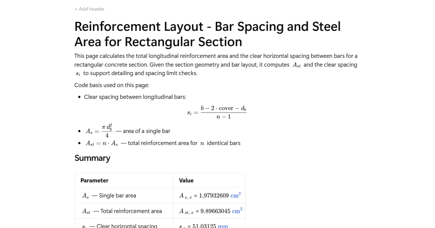
This calculator determines the total longitudinal reinforcement area and the clear horizontal spacing between bars for a rectangular concrete section. Given the section geometry and bar layout, it computes the single bar area, total steel area, and clear spacing to support detailing and code compliance checks per ACI 318-19.
- Structural engineer — confirm that bar spacing and total steel area meet detailing requirements for beams or columns without manually stepping through each formula.
- Reinforced concrete designer — iterate quickly on bar size and number to hit a target steel area or satisfy minimum and maximum spacing limits before finalising drawings.
- CAD detailer or checking engineer — verify reinforcement layouts against section geometry and cover as a fast, auditable cross-check during drawing review.
This is an engineering-grade calculator built on CalcTree, where every formula is transparent, traceable, and tied to the relevant ACI 318-19 clause.
More Info on Reinforcement Layout - Bar Spacing and Steel Area for Rectangular Section
Inputs
The calculator takes two categories of input: section geometry and reinforcement layout. Geometry inputs are the section width, total depth, and clear cover to the outermost reinforcement. Reinforcement inputs are the bar diameter, selected from a standard size list, and the number of bars placed in a single layer across the section width. Clear cover is the distance from the concrete face to the nearest bar surface, which directly affects the available width for bar placement and spacing.
How Bar Spacing is Calculated
Clear horizontal spacing is the net distance between adjacent bar surfaces in the same layer. The formula subtracts twice the cover and one bar diameter from the total section width to get the usable span between the outermost bar centrelines, then divides by the number of spaces, which is one less than the number of bars. This produces the clear gap between adjacent bars rather than the centre-to-centre pitch. The result maps directly to the minimum clear spacing requirements in ACI 318-19 Clause 25.2.1, which govern constructability, concrete placement, and aggregate consolidation.
How Steel Area is Calculated
The area of a single bar is computed from the bar diameter using the standard circular area formula. Total reinforcement area is then the product of the single bar area and the number of bars. Both results are referenced to ACI 318-19 Clause 25.2 and expressed in consistent area units. These values feed directly into section capacity checks, minimum and maximum steel ratio verification, and reinforcement scheduling.
Outputs and Design Checks
The calculator returns three output values: the area of a single bar, the total longitudinal steel area for the specified bar count, and the clear horizontal spacing between bars. The spacing result should be compared against the ACI 318-19 minimum clear spacing limit, which is the greatest of the bar diameter, 25 mm, and four-thirds the maximum aggregate size. The total steel area supports checks on minimum and maximum reinforcement ratios for the section. These outputs are presented in a summary table for direct use in design reports or further capacity calculations.
Common Calculation Errors to Avoid
- Using centre-to-centre spacing instead of clear spacing — the formula and code limits reference the clear distance between bar surfaces, not the pitch between centrelines. Confusing the two can result in layouts that violate minimum spacing requirements.
- Applying the wrong cover definition — clear cover is measured to the bar surface, not to the stirrup or tie. If the section has transverse reinforcement, the longitudinal bar cover must account for the stirrup diameter separately.
- Assuming bars fit without checking available width — a large number of bars or oversized bars can result in negative or near-zero clear spacing. Always confirm the computed spacing is positive and meets the code minimum before proceeding.
- Using nominal bar diameter inconsistently — the same diameter value must be used in both the area formula and the spacing formula. Mixing nominal and actual dimensions, or switching between inch-based and metric designations mid-calculation, introduces error in both outputs.
- Forgetting that this applies to a single layer — the spacing formula assumes all bars are placed in one horizontal layer. For multi-layer arrangements, each layer must be assessed separately with its own cover and bar count.
- Neglecting to check against maximum spacing limits — minimum steel area requirements can be satisfied with few, widely spaced bars, but code also imposes maximum spacing limits for crack control. The spacing output from this calculator must be checked against both the minimum and maximum limits for the application.
Engineering templates
Common calculators
Design guides
FAQs
What does this calculation actually compute?
Given a rectangular concrete section geometry and bar layout, the page outputs three things: the area of a single bar (A_s), the total longitudinal steel area (A_st), and the clear horizontal spacing between bars (s_i). These are the numbers you need before running spacing limit checks to code.
What is clear spacing and why does it matter?
Clear spacing is the gap between the faces of adjacent bars, not centre-to-centre distance. It controls whether concrete can flow between bars during placement and consolidation. ACI 318-19 Cl. 25.2.1 sets a minimum clear spacing to avoid segregation and ensure bond development — this calculation gives you s_i directly so you can check it against that limit.
How is the clear spacing formula derived?
The total horizontal space available for bar gaps is the section width minus two covers and one bar diameter. That remaining length is divided by (n − 1) gaps between n bars, giving s_i = (b − 2·cover − d_b) / (n − 1). The formula assumes all bars are equally spaced in a single layer.
What cover value should I enter?
Enter the clear cover to the longitudinal bar face, not to the stirrup or tie. If stirrups are present, your clear cover to the main bar is the specified cover plus the stirrup bar diameter. This distinction affects both the spacing result and your detailing drawings.
Can I check multiple bar sizes or counts quickly?
Yes. The bar diameter is a dropdown of standard imperial bar sizes (#2 through #8) and the number of bars is a direct numeric input. Adjust either and the outputs update instantly, making it straightforward to compare layout options for a given section.
Does this calculation verify that spacing limits are satisfied?
No — it computes s_i and A_st but does not run the code limit check itself. You use the outputs here as inputs to a separate spacing check against ACI 318-19 minimums (typically the largest of 25 mm, 1.0·d_b, or 4/3 times the maximum aggregate size). Keep this page as the geometry step in your broader detailing workflow.
Learn about the benefits of using CalcTree on engineering projects!