Check ACI 318-19 §16.2.6.2 minimum end distance for precast slabs and beams instantly. Verify l_prov ≥ l_min in seconds. Try it free on CalcTree.

This template is not available yet. You can sign up and create it yourself!
Or let us know if you'd like to be notified when it’s ready:

No items found.
No items found.
About this ACI 318-19: Precast connections - Minimum design distance from face of support to end of member (16.2.6.2) Calculator
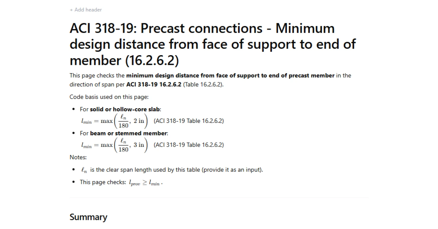
This calculator checks the minimum required distance from the face of a support to the end of a precast member in the direction of span, per ACI 318-19 Table 16.2.6.2. It covers both solid or hollow-core slabs and beams or stemmed members, computing the governing minimum distance from the clear span fraction and the fixed code floor, then comparing it against the provided distance to return a pass/fail result.
- Structural engineer — verify precast connection geometry against ACI 318-19 requirements during design or peer review without manually parsing the table.
- Precast specialist — quickly confirm that bearing setbacks on corbels, ledger beams, or wall seats meet the code minimum for the member type and span length being detailed.
- Plan checker or EOR — run a traceable, documented check on precast end distance that can be saved directly to a project file and shared with the design team.
This is an engineering-grade calculator on CalcTree that follows ACI 318-19 exactly, exposes every intermediate value, and produces a clear pass/fail output you can audit and include in a calculation package.
More info on ACI 318-19: Precast connections - Minimum design distance from face of support to end of member (16.2.6.2)
Inputs
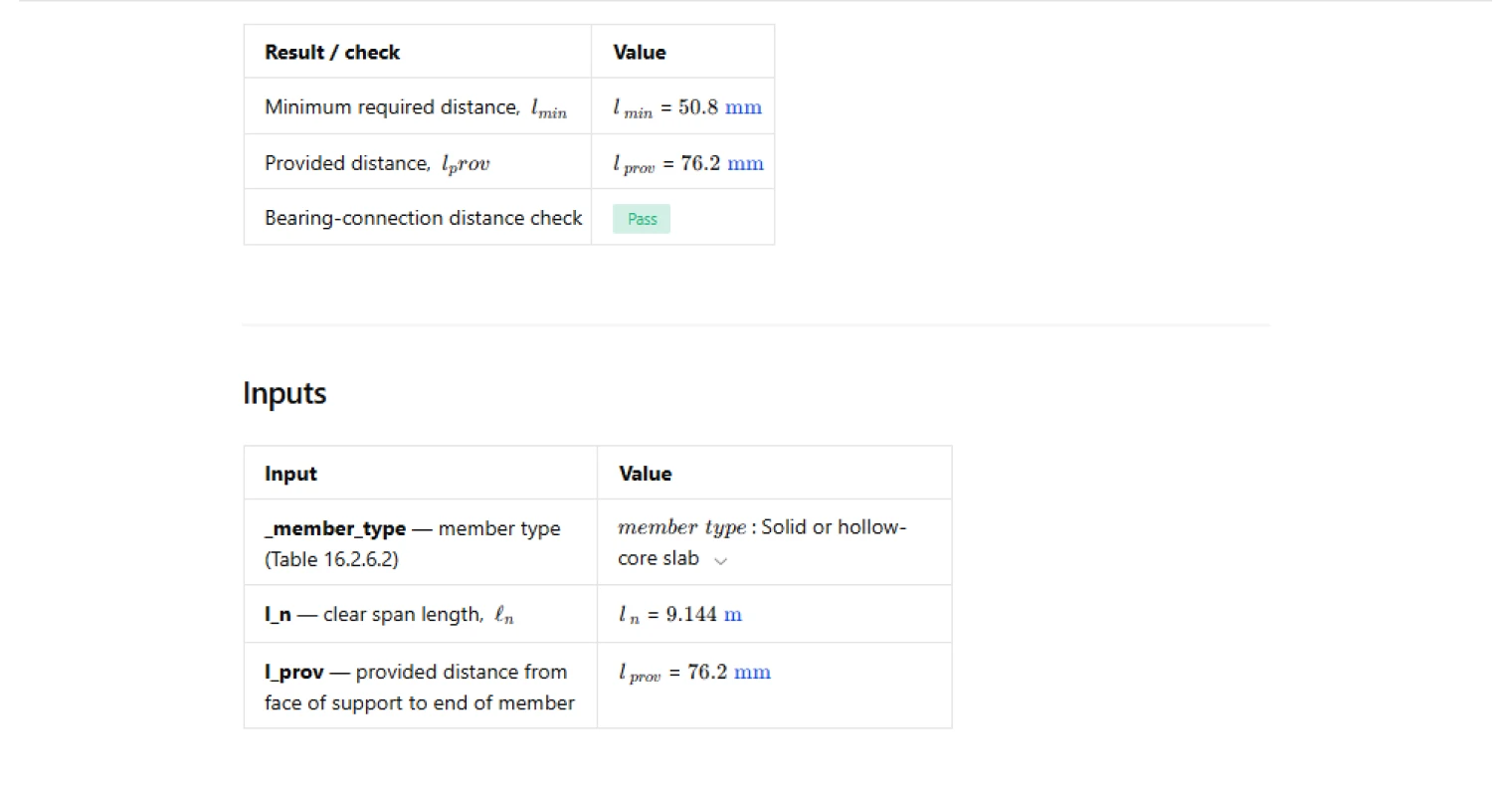
The calculator takes three inputs. The member type is selected from a dropdown — either solid or hollow-core slab, or beam or stemmed member — which determines which code branch and fixed minimum apply. The clear span length is entered as a length dimension and drives the span-based candidate distance. The provided distance is the actual distance from the face of the support to the end of the precast member as detailed or installed, and this is the value that gets checked against the computed minimum.
How the minimum distance is calculated
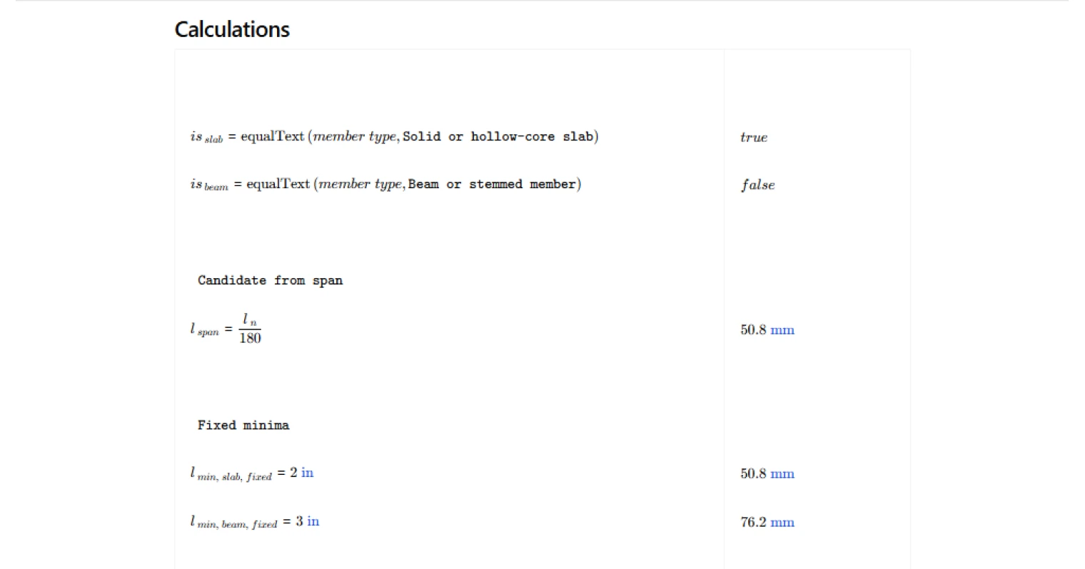
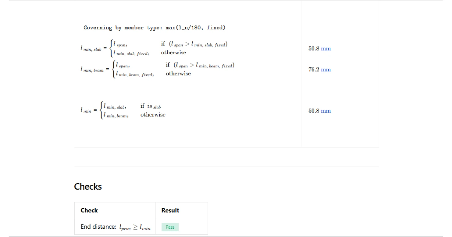
The minimum distance is computed per ACI 318-19 Table 16.2.6.2 using a two-branch approach. For both member types, a span-based candidate is first derived by dividing the clear span length by 180. That candidate is then compared against a fixed code floor — two inches for solid or hollow-core slabs and three inches for beams or stemmed members — and the larger of the two governs. The member type selection routes the calculation to the correct branch, so only the applicable minimum is reported.
Design check
The check compares the provided distance against the governing minimum distance. If the provided distance is greater than or equal to the minimum, the check returns a pass. If it falls short, it returns a fail. The result is displayed as a traffic light indicator alongside both values in the summary table, giving an immediate read on whether the detailing meets the code requirement without having to manually interpret intermediate results.
Outputs
The calculator reports the minimum required distance and the provided distance side by side in a summary table, followed by the pass/fail status of the bearing-connection distance check. All values carry units, and the logic is fully transparent — the span-based candidate, the fixed minimum, and the governing result are all computed in sequence so the basis of the minimum is clear. The output is suitable for direct inclusion in a precast connection calculation package submitted for review.
Common Calculation Errors to Avoid
- Using the total span instead of the clear span — ACI 318-19 Table 16.2.6.2 requires the clear span length, not the center-to-center span. Using the full span overstates the span-based candidate and can produce a non-conservative minimum.
- Applying the wrong member type — the fixed minimum floor differs between slabs and beams or stemmed members. Selecting the slab branch for a beam or stemmed member will understate the minimum required distance.
- Ignoring the fixed minimum floor — for short spans, the span-based term may be very small, but the code imposes an absolute lower bound regardless. Reporting only the span-derived value without checking it against the fixed minimum is non-conservative.
- Measuring the provided distance incorrectly — the distance is measured from the face of the support to the end of the precast member in the direction of span, not to the centerline of a bearing pad or the edge of a seat. Confirm the measurement reference before entering the value.
- Conflating bearing length with end distance — the minimum end distance checked here is distinct from the required bearing length. Both must be satisfied independently; passing this check does not confirm bearing area adequacy.
Engineering templates
Common calculators
Design guides
FAQs
What does ACI 318-19 Section 16.2.6.2 actually require for precast member end distances?
ACI 318-19 Table 16.2.6.2 sets a minimum distance measured in the direction of span from the face of the support to the end of the precast member. For solid or hollow-core slabs, that minimum is the greater of l_n/180 or 2 in. For beams or stemmed members, it is the greater of l_n/180 or 3 in. The fixed floor values ensure a practical minimum regardless of how short the span is.
Why does the code use l_n/180 as the span-based term?
The l_n/180 ratio accounts for the fact that longer-spanning members experience greater relative displacement and rotation at their ends under load and under differential settlement. A longer member needs more distance from the face of support to accommodate movement without the end walking off the bearing surface. The fixed minimums of 2 in or 3 in then guard against unrealistically small values on short spans.
What is l_n and how should I measure it for this calculation?
l_n is the clear span length of the precast member, measured from face of support to face of support. Do not use the center-to-center span. The face of the support is typically the inner edge of the bearing ledge, corbel, or wall. Enter this value directly as an input in the calculator.
What is l_prov and where do I measure it from?
l_prov is the distance you are providing from the face of the support to the physical end of the precast member, measured in the direction of span. It is essentially how far the member end extends beyond the face of the support, which is the opposite of the bearing length. Check your shop drawings or connection details to confirm this dimension before entering it.
How do I know which member type to select in the calculator?
Select "Solid or hollow-core slab" for flat precast deck elements, whether solid or with longitudinal voids. Select "Beam or stemmed member" for rectangular beams, inverted tee beams, double tees, and single tees. The selection controls which fixed minimum floor value applies: 2 in for slabs and 3 in for beams and stemmed members.
The check is failing — what are my options to resolve it?
A failing result means l_prov is less than l_min. You have two practical paths: increase the physical end distance by extending the member further onto the support, or revisit the support geometry to move the face of the support closer to the member end. If the span is long and l_n/180 governs, check whether the clear span input is correct, as an error there is a common cause of unexpected failures.
Learn about the benefits of using CalcTree on engineering projects!