Check ACI 318-19 plain concrete walls for flexure and axial compression (14.5.4). Instant pass/fail results. Try the free CalcTree template now.

This template is not available yet. You can sign up and create it yourself!
Or let us know if you'd like to be notified when it’s ready:


No items found.
No items found.
About this Plain Concrete Wall Calculator
This calculator checks plain concrete wall capacity for combined axial compression and out-of-plane flexure in accordance with ACI 318-19 Clause 14.5.4. It supports both the full Table 14.5.4.1 interaction approach (tension-face stress check plus compression-face interaction) and the simplified alternative in 14.5.4.2 when the middle-third condition is satisfied for a solid rectangular wall.
- Structural engineer — verify whether a plain wall strip is permitted and adequate under a governing factored axial force and moment, and confirm which face governs.
- Building engineer — run quick “is this wall proportioned OK?” checks during concept or value engineering before committing to reinforced detailing.
- Forensic engineer — back-check an existing plain wall against the code interaction limits using reported loads and basic section dimensions.
The page exposes the intermediate section properties, nominal strengths, interaction terms, and pass/fail indicators so the checks are auditable. It’s an engineering-grade calculator on CalcTree you can review, save to a project, and reuse consistently across jobs.
More info on Plain Concrete Wall Design
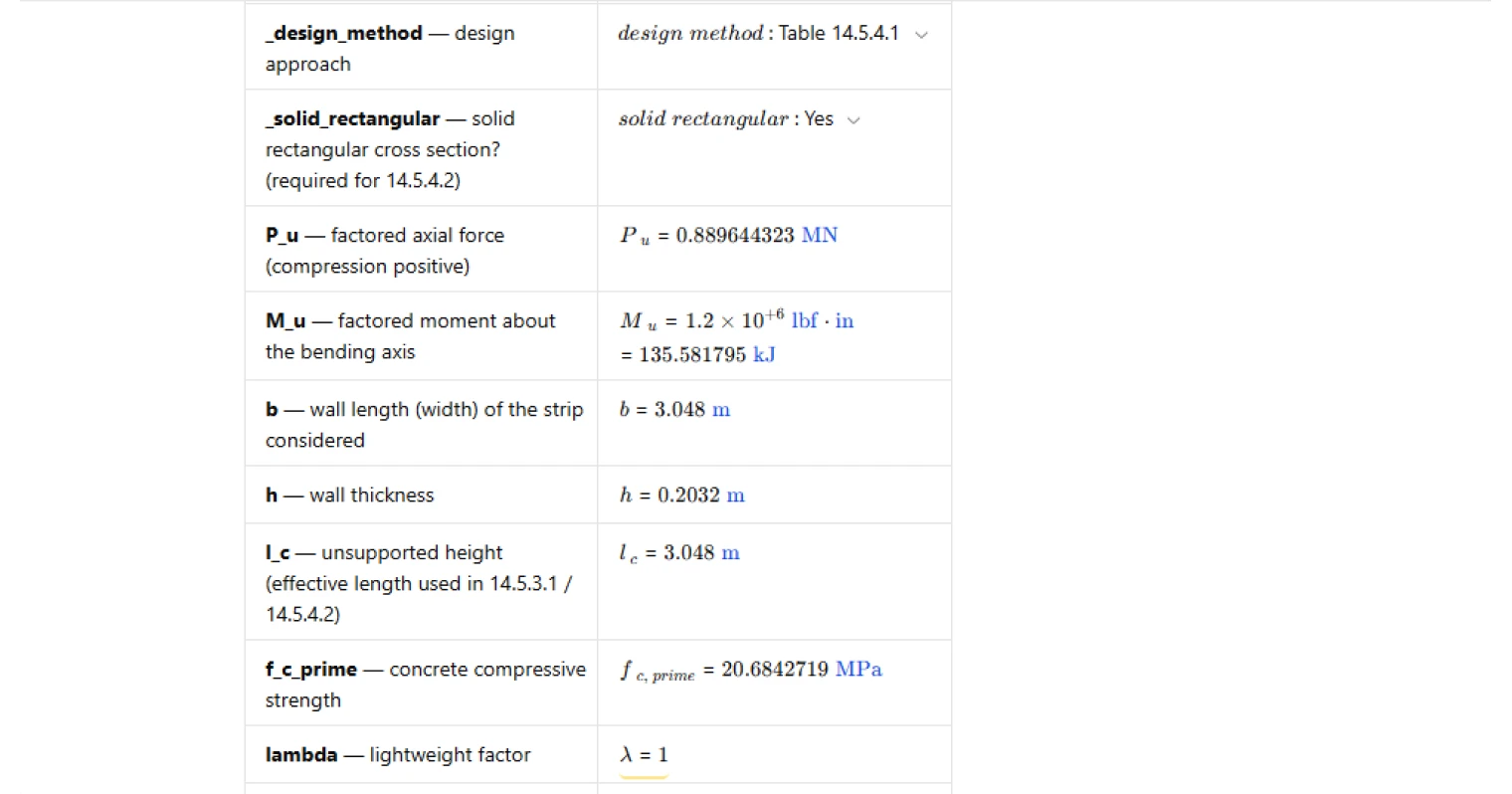
Inputs and assumptions
The calculator takes factored axial load and factored moment with a consistent sign convention (axial compression taken as positive). Geometry is defined as a rectangular wall strip with length (strip width) and thickness, plus the unsupported height used by the plain-wall slenderness terms. Concrete strength and lightweight factor are included, along with a user-specified strength reduction factor for the checks.
Elastic section modulus at each extreme face can be overridden; otherwise the tool uses the symmetric rectangular section modulus about the bending axis for both faces.
Section properties and nominal strengths
Gross area is computed from the wall strip dimensions, and the default elastic section modulus is taken from the standard rectangular expression.
Nominal strengths are then evaluated using the referenced plain concrete wall equations:
- Nominal moment strength is based on concrete stress times the compression-face section modulus.
- Nominal axial strength is based on concrete stress times gross area, reduced by the wall slenderness bracket term derived from the unsupported height-to-thickness ratio, with a guard to prevent negative bracket values.
Design strengths are obtained by applying the strength reduction factor to the nominal axial and moment strengths for use in the interaction checks.
Table 14.5.4.1 interaction checks
The Table method evaluates two separate limit states:
- A tension-face combined stress demand formed from the sum of flexural stress (moment divided by tension-face section modulus) and axial stress (axial force divided by gross area), checked against the Table tension-face limit expressed in terms of the concrete strength square root, lightweight factor, and strength reduction factor.
- A compression-face interaction ratio formed from the sum of normalized demands on moment strength and axial strength, checked against a unity limit.
The calculator reports both the demand and limit terms so you can see whether a failure is driven by the elastic stress check on the tension face or by the strength interaction on the compression face.
Simplified option per 14.5.4.2
When the wall is a solid rectangular section and the factored moment is small enough that the resultant remains within the middle third of the thickness, the simplified alternative is permitted. In that case, the moment is not explicitly considered and the axial capacity is evaluated using the simplified axial equation in 14.5.4.2 (with the same slenderness bracket term concept).
If the user selects the simplified method, the page enforces eligibility (solid rectangular plus middle-third condition) and then checks the factored axial force against the simplified design axial strength.
Common Calculation Errors to Avoid
- Mixed sign convention for axial force — keep compression positive throughout, or the middle-third eligibility and interaction terms will be evaluated incorrectly.
- Using the wrong section modulus — ensure the bending axis matches the intended wall strip orientation, and only override face section moduli when the section is truly non-symmetric or you have a justified effective section.
- Omitting the slenderness bracket logic — the plain wall axial equations include a reduction based on unsupported height-to-thickness; ignoring it can materially overstate axial capacity.
- Applying the simplified method when not permitted — 14.5.4.2 requires a solid rectangular wall and a middle-third condition; do not use it for non-rectangular sections or large eccentricity.
- Unit handling for the square-root concrete term — the tension-face limit is an empirical stress form; inconsistent unit treatment around the square-root term can corrupt the limit stress.
- Assuming both faces use the same S when overriding — for asymmetric sections, tension- and compression-face section moduli can differ; apply the correct face value to each check.
Engineering templates
Common calculators
Design guides
FAQs
What does ACI 318-19 Section 14.5.4 actually check for plain concrete walls?
Section 14.5.4 checks that a plain concrete wall can handle the combined effect of factored moment and factored axial compression without exceeding the material's capacity at either face. The tension face is checked against a stress limit based on the modulus of rupture (5λ√f′c), since plain concrete has no rebar to carry tension. The compression face is checked via an interaction ratio combining moment and axial demand against nominal strengths. Both checks must pass unless you qualify for and select the simplified method under 14.5.4.2.
What is the difference between the Table 14.5.4.1 method and the simplified 14.5.4.2 method?
The Table 14.5.4.1 method runs two separate interaction checks — one at the tension face for net stress and one at the compression face for combined M and P capacity. It applies to any plain concrete wall section. The simplified 14.5.4.2 method is only permitted for solid rectangular walls where the moment is small enough that the resultant stays within the middle third of the wall thickness (Mu ≤ Pu·h/6). When that condition holds, you can ignore the moment entirely and check only axial capacity using a reduced nominal strength formula (0.45f′c instead of 0.60f′c). The simplified method trades a more conservative axial capacity for the convenience of ignoring moment.
Why does the tension-face check use an elastic section modulus rather than a plastic or cracked section approach?
Plain concrete is treated as an unreinforced, brittle material. ACI 318-19 requires linear-elastic stress distribution for plain concrete members because there is no reinforcement to redistribute load after cracking. The elastic section modulus Sm captures the stress at the extreme fiber under combined bending and axial load, which is the governing failure criterion — concrete cracks when that tensile stress exceeds the modulus of rupture limit.
How do I input the section modulus for a non-rectangular or non-symmetric wall section?
By default, the calculation uses Sm = bh²/6, which is correct for a solid rectangular section symmetric about the bending axis. If your wall cross-section is non-rectangular or non-symmetric (for example, a T-section or a wall with reveals), enter the actual elastic section moduli for the tension and compression faces directly using the S_m_tension and S_m_compression override inputs. Any nonzero value entered there will replace the rectangular default. Note that the simplified 14.5.4.2 method is not available for non-rectangular sections — set the solid rectangular flag to No in that case.
What sign convention applies to Pu and Mu, and does it matter which face is in tension?
The calculation takes Pu as positive in compression and Mu as a magnitude. For a symmetric rectangular section, the same Sm applies to both faces, so the direction of bending only affects which face is in tension. If your section is symmetric, no adjustment is needed. For non-symmetric sections, you must supply the correct Sm for the face being checked, since the tension-face limit is the critical one for plain concrete — a net tensile stress exceeding φ(5λ√f′c) at the extreme fiber will cause cracking and failure.
What value should I use for the strength reduction factor φ?
ACI 318-19 Table 21.2.1 gives φ = 0.60 for plain concrete members in general. However, some jurisdictions or project-specific requirements may use φ = 0.65, which matches the default in this template. Confirm the applicable φ with your project specifications or local code amendments before running the check. The same φ value is applied to both the tension-face stress limit and the compression-face nominal strengths Mn and Pn.
Learn about the benefits of using CalcTree on engineering projects!