Calculate plain concrete axial compression strength per ACI 318-19 14.5.3.1. Instant Pn results with slenderness check. Try it free on CalcTree.

This template is not available yet. You can sign up and create it yourself!
Or let us know if you'd like to be notified when it’s ready:


No items found.
No items found.
About this ACI 318-19: Plain Concrete - Axial Compression Nominal Strength (14.5.3.1) Calculator
This calculator computes the nominal axial compression strength of plain concrete members per ACI 318-19 Section 14.5.3.1. It applies the code's slenderness-modified formula directly, evaluates the factored demand against the computed nominal strength, and returns a clear pass/fail check — all in a single, traceable page.
- Structural engineer — verify plain concrete walls, pedestals, or piers under axial load, with the slenderness term and bracket factor exposed for quick review.
- Building designer — run geometry iterations on member thickness and effective length to confirm compliance without manual formula work.
- Plan checker or reviewer — audit the full calculation path from inputs through to the demand-capacity check in one place.
This is an engineering-grade calculator built on CalcTree, where calculations are live, unit-aware, and ready to attach to a project record or share with a team.
More Info on ACI 318-19: Plain Concrete - Axial Compression Nominal Strength (14.5.3.1)
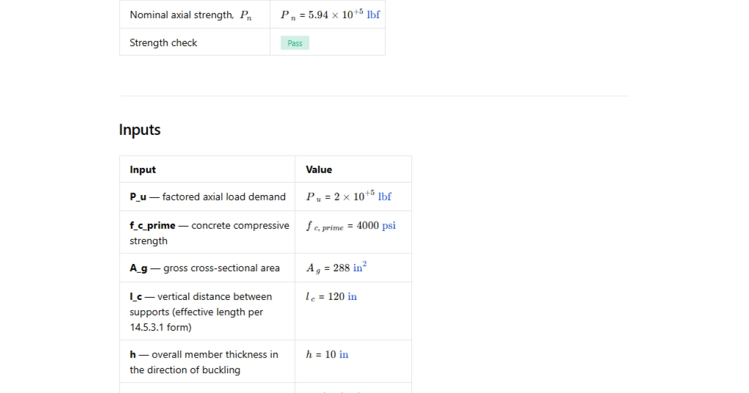
Inputs
The calculation requires five geometric and material inputs. Concrete compressive strength and gross cross-sectional area define the baseline capacity of the section. The effective length of the member and its overall thickness in the direction of buckling together determine the slenderness term that reduces that baseline capacity. The factored axial load demand is entered to enable the demand-capacity check. Units must be kept consistent across geometry and force inputs to avoid scaling errors in the output.
How Nominal Strength is Calculated
ACI 318-19 Section 14.5.3.1 gives the nominal axial compression strength as a function of concrete strength, gross area, and a slenderness reduction factor. The slenderness term is formed by dividing the effective length by the product of 32 and the member thickness. That term is squared and subtracted from unity to form a bracket factor, which is then multiplied by the concrete strength, gross area, and the coefficient 0.60. As slenderness increases, the bracket factor decreases, reducing the nominal strength. The formula reflects braced or restrained end conditions typical of plain concrete elements, as noted in the ACI commentary.
Outputs and Design Check
The calculator returns the slenderness term, the nominal axial strength, and a demand-capacity check comparing the factored axial load to the computed nominal strength. The check can be toggled on or off using the apply-checks selector, which is useful when the page is being used purely to compute capacity without a specific demand. When checks are active, the result displays as a clear pass or fail. No strength reduction factor is applied on this page — the result is the nominal strength only, and users should apply the appropriate capacity reduction factor separately if required by their design workflow.
Scope and Limitations
This calculation applies specifically to plain concrete compression members as defined in ACI 318-19 Chapter 14. It does not cover reinforced concrete columns, walls with minimum reinforcement meeting Chapter 11 requirements, or members subject to significant bending in addition to axial load. The formula is valid within the slenderness range implied by the code expression; members with very high slenderness ratios may fall outside the intended application of this provision, and the engineer should confirm that the member geometry is consistent with the plain concrete classification before relying on these results.
Common Calculation Errors to Avoid
- Using the wrong dimension for h — h is the overall thickness in the direction of buckling, not necessarily the smaller cross-sectional dimension. Confusing these will produce an incorrect slenderness term and an unconservative strength.
- Inconsistent units between l_c and h — both must be in the same length unit before computing the slenderness ratio. Mixing inches and feet will give a bracket factor that is completely wrong.
- Applying a strength reduction factor inside this formula — the ACI 318-19 expression gives the nominal strength only. The capacity reduction factor φ is applied separately and should not be folded into the inputs or confused with the 0.60 coefficient in the formula.
- Treating this formula as applicable to reinforced members — the Section 14.5.3.1 provision is specific to plain concrete. Using it for members with longitudinal reinforcement underestimates capacity and applies an incorrect model.
- Ignoring the slenderness limit implied by the code — if the slenderness term approaches or exceeds 1.0, the bracket factor goes to zero or negative, signalling that the member geometry is outside the scope of this expression. Check that your member proportions are appropriate before accepting the result.
- Confusing gross area with net area — A_g is the full gross cross-sectional area of the plain concrete member. Deducting voids or openings without code basis will produce an artificially low nominal strength.
Engineering templates
Common calculators
Design guides
FAQs
What does ACI 318-19 Section 14.5.3.1 cover?
Section 14.5.3.1 gives the equation for nominal axial compression strength of plain concrete members. Plain concrete relies entirely on the gross section with no reinforcement contribution, so the code applies a 0.60 factor to f'c and reduces capacity further as slenderness increases. It applies to walls, pedestals, and similar elements designed under Chapter 14.
Why does slenderness reduce plain concrete axial strength?
The term [1 - (lc / 32h)²] penalizes members that are long relative to their thickness. Slender plain concrete elements are more susceptible to buckling and second-order effects than reinforced members, and because there is no steel to redistribute stress, the code builds the stability reduction directly into the nominal strength equation rather than applying a separate moment magnifier.
What is the difference between lc and h in this calculation?
lc is the vertical distance between supports, representing the unsupported length of the member. h is the overall thickness of the cross-section in the direction being checked for buckling. The ratio lc / 32h is the slenderness term; a higher ratio means more capacity reduction. Use consistent units for both inputs or the slenderness term will be wrong.
When does the slenderness term become critical?
When lc / 32h approaches 1.0, the bracket term approaches zero and Pn drops sharply. In practice, keep the slenderness ratio well below 1.0. For the default example on this page (lc = 120 in, h = 10 in), the ratio is 0.375, which is a moderate slenderness and leaves meaningful capacity. Very thin walls under tall unsupported heights are where this reduction becomes a controlling factor.
How do I use the strength check on this page?
Enter your factored axial demand Pu alongside the geometry and material inputs. Set the apply checks toggle to Yes, and the page will compare Pu against the calculated Pn and return a Pass or Fail result. If you want to explore Pn values without triggering the demand check, set the toggle to No and the check reports N/A.
Can this template be used for reinforced concrete walls?
No. The ACI 318-19 Section 14.5.3.1 equation is specific to plain concrete members with no longitudinal reinforcement. For reinforced concrete walls, use the Chapter 11 wall design provisions with separate equations that account for reinforcement contribution to axial and flexural strength.
Learn about the benefits of using CalcTree on engineering projects!