Check ACI 318-19 Cl. 8.6.1 minimum flexural reinforcement for two-way slabs instantly. Covers base and shear-triggered minimums. Try it free on CalcTree.

This template is not available yet. You can sign up and create it yourself!
Or let us know if you'd like to be notified when it’s ready:


No items found.
No items found.
About this ACI 318-19: Minimum Flexural Reinforcement – Nonprestressed Two-Way Slabs (Cl. 8.6.1) Calculator
This calculator checks minimum flexural reinforcement requirements for nonprestressed two-way slabs per ACI 318-19 Cl. 8.6.1. It evaluates both the base minimum steel area from Cl. 8.6.1.1 and the additional minimum triggered near columns or concentrated loads when two-way shear stress is high per Cl. 8.6.1.2. Provided steel area is computed directly from bar size and spacing for one or two reinforcement layers.
- Structural engineer — verify minimum slab reinforcement compliance in a single pass, with the Cl. 8.6.1.2 trigger evaluated automatically so nothing is missed at high-shear regions.
- Slab designer — iterate on bar size, spacing, and layer count to efficiently meet the governing minimum without over-designing.
- Checking engineer — audit every parameter and intermediate result against the code equations for independent review or peer-check.
This is an engineering-grade calculator on CalcTree that exposes all intermediate values for full traceability and can be saved, shared, and linked within a project workspace.
More info on ACI 318-19: Minimum Flexural Reinforcement – Nonprestressed Two-Way Slabs (Cl. 8.6.1)
Inputs
The calculator takes three groups of inputs. Geometry and material inputs include slab thickness, slab width over which reinforcement is provided, specified concrete compressive strength, the lightweight concrete modification factor, reinforcement yield strength, the shear strength reduction factor, and the column location factor per Cl. 22.6.5.3. Two-way shear inputs include the factored direct shear stress at the critical section and the critical perimeter length, which together determine whether the elevated shear threshold in Cl. 8.6.1.2 is triggered. Reinforcement inputs allow selection of one or two bar layers, with bar size chosen from a standard rebar menu and spacing entered for each layer.
Design Checks and Code Basis
Two code checks are applied in sequence. The base minimum from Cl. 8.6.1.1 sets the steel area as a fixed ratio of the gross concrete area, using a minimum reinforcement ratio of 0.0018 applied to the product of slab width and thickness. The additional minimum from Cl. 8.6.1.2 is only evaluated when the factored two-way shear stress exceeds the trigger threshold, which is a function of the shear reduction factor, the lightweight modification factor, and the square root of the specified concrete strength. When the threshold is exceeded, a second minimum steel area is computed as a function of the shear stress, slab width, critical perimeter, shear reduction factor, column location factor, and reinforcement yield strength. The governing required area is the larger of whichever checks apply.
Provided Steel Area
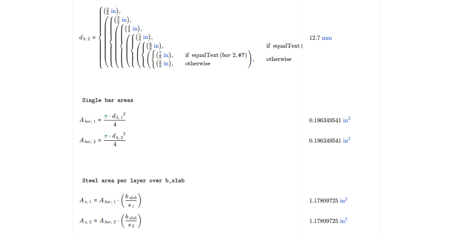
Provided steel area is calculated from first principles using bar diameter and spacing rather than requiring the user to look up tabulated bar areas. For each active layer, the individual bar cross-sectional area is derived from the selected bar diameter, and the total layer contribution is found by multiplying that area by the number of bars fitting within the specified slab width at the given spacing. When two layers are selected, both contributions are summed to give the total provided area. This approach makes it straightforward to iterate on bar size and spacing to efficiently satisfy the governing minimum.
Outputs
The summary outputs include the base minimum steel area from Cl. 8.6.1.1, the trigger shear stress level for Cl. 8.6.1.2, the governing minimum required steel area, the total provided steel area, and a pass/fail check confirming whether the provided area meets or exceeds the requirement. All results carry units and are presented alongside the input values so the full calculation is self-contained and auditable.
Common Calculation Errors to Avoid
- Neglecting the Cl. 8.6.1.2 check entirely — the additional minimum near columns is easy to overlook when designing for flexure alone; always evaluate the shear stress trigger, particularly at interior columns with high gravity loads.
- Using the wrong slab width — the slab width input governs both the gross area calculation and the provided steel area; using a tributary or strip width inconsistent with how reinforcement is actually distributed leads to incorrect results in both directions.
- Applying the wrong column location factor — the value of the column location factor differs for interior, edge, and corner columns per Cl. 22.6.5.3; using the interior column value everywhere is unconservative for edge and corner cases.
- Ignoring the lightweight modification factor — for lightweight concrete, the modification factor reduces the shear trigger threshold, making it easier to activate the Cl. 8.6.1.2 minimum; using a value of 1.0 for lightweight concrete is unconservative.
- Miscounting reinforcement layers — including a second layer in the provided area calculation when only one layer is physically placed inflates the provided steel and can mask a deficiency.
- Taking the square root of concrete strength in the wrong units — the empirical shear stress equations require concrete strength in psi before taking the square root; using MPa without conversion produces an incorrect trigger threshold and shear-based minimum.
Engineering templates
Common calculators
Design guides
FAQs
What does ACI 318-19 Cl. 8.6.1 require for minimum flexural reinforcement in two-way slabs?
Cl. 8.6.1.1 sets a base minimum steel area of 0.0018 times the gross concrete area (As,min = 0.0018 × Ag). This applies across the full slab width regardless of loading. An additional, typically higher minimum kicks in under Cl. 8.6.1.2 when two-way shear stress near a column or concentrated load exceeds φv × 2λ√f'c. That second threshold is meant to ensure adequate ductility where punching shear demand is significant.
When does the Cl. 8.6.1.2 additional minimum apply, and how is it calculated?
The additional minimum triggers when the factored direct shear stress vuv exceeds the limit φv × 2λ√f'c at the critical perimeter. Once triggered, the required area is computed as As,min = 5 × vuv × bslab × bo / (φv × αs × fy). This formula depends on the critical perimeter length bo and the column location factor αs, which takes values of 40, 30, or 20 for interior, edge, or corner columns respectively per Cl. 22.6.5.3. The calculation uses whichever of the two minimums governs.
What is the column location factor αs and how do I choose the right value?
αs reflects where the column sits relative to the slab boundary. Use 40 for interior columns, 30 for edge columns, and 20 for corner columns. These values come from ACI 318-19 Cl. 22.6.5.3 and directly affect the Cl. 8.6.1.2 minimum steel area. A lower αs at edge or corner columns produces a larger required steel area for the same shear stress, which is consistent with the reduced critical perimeter and less redundancy at those locations.
How does the calculator compute the provided steel area?
The tool computes steel area from bar size and spacing inputs over the specified slab width bslab. You select a bar designation from #2 through #8, enter the spacing, and the page calculates the single bar area from π × db² / 4 and multiplies by bslab / s. If two reinforcement layers are selected, both layers contribute and the total provided area is their sum.
What width should I use for bslab when checking this clause?
Use the slab width over which the reinforcement being checked is uniformly distributed. This is typically the column strip or middle strip width depending on which band of steel you are evaluating, not the full bay width. Be consistent between the width used for the provided steel calculation and the width input to the formula, as bslab appears directly in the Cl. 8.6.1.2 expression.
Does this calculation cover all reinforcement requirements for a two-way slab design?
No. This page checks minimum flexural reinforcement only per Cl. 8.6.1, including the shear-triggered additional minimum. It does not check flexural demand-based reinforcement from moment design, punching shear capacity, maximum bar spacing, or development length requirements. Use this template as one step in a broader two-way slab design workflow.
Learn about the benefits of using CalcTree on engineering projects!