ACI 318-19 Cl. 8.4.4.2 two-way shear stress with moment transfer calculator. Computes γf, γv, and v_u at faces AB/CD. Try it free on CalcTree.

This template is not available yet. You can sign up and create it yourself!
Or let us know if you'd like to be notified when it’s ready:


No items found.
No items found.
About this ACI 318 Moment Transfer by Shear Calculator
This calculator evaluates factored two-way shear stress at a slab–column connection when moment is transferred due to eccentric shear, following ACI 318-19 Clause 8.4.4.2. It determines how the slab moment is distributed between flexure and shear eccentricity and calculates the resulting shear stress distribution along the critical perimeter.
- Structural engineer — assess punching shear stresses at slab-column connections where slab moments are transferred through eccentric shear.
- Building designer — quickly verify how moment transfer affects shear stresses around a column critical section.
- Engineering reviewer — audit how moment transfer fractions and shear stresses are derived under ACI 318 provisions.
The calculator exposes all intermediate parameters used in the code provisions, allowing engineers to trace the distribution of moment transfer and resulting shear stresses. It’s an engineering-grade calculator that can be audited, reused, and embedded in calculation reports within CalcTree.
More info on ACI 318 Moment Transfer by Shear
Critical section geometry and baseline shear
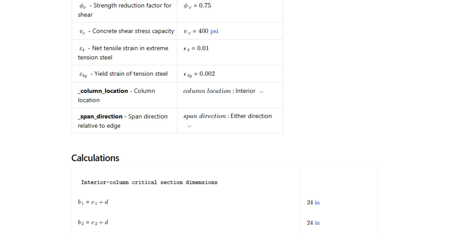
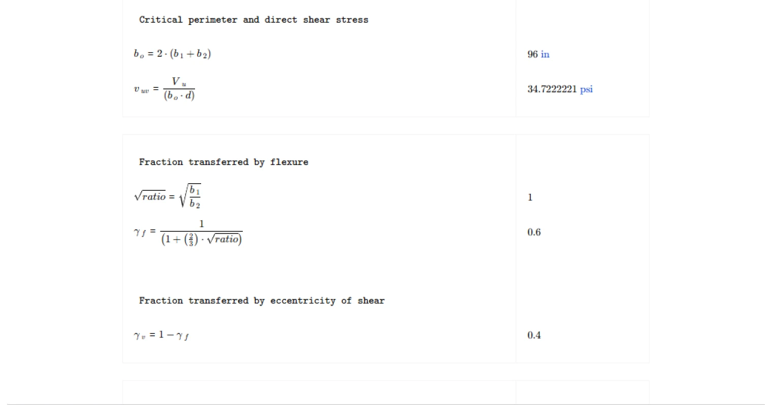
The calculation begins by defining the critical punching shear perimeter around the column using the effective slab depth and column dimensions. From this perimeter, the calculator determines the direct shear stress caused by the factored shear force acting at the connection.
This baseline shear stress represents the uniform component of shear around the critical section before the additional effects of moment transfer are considered.
Moment transfer fractions
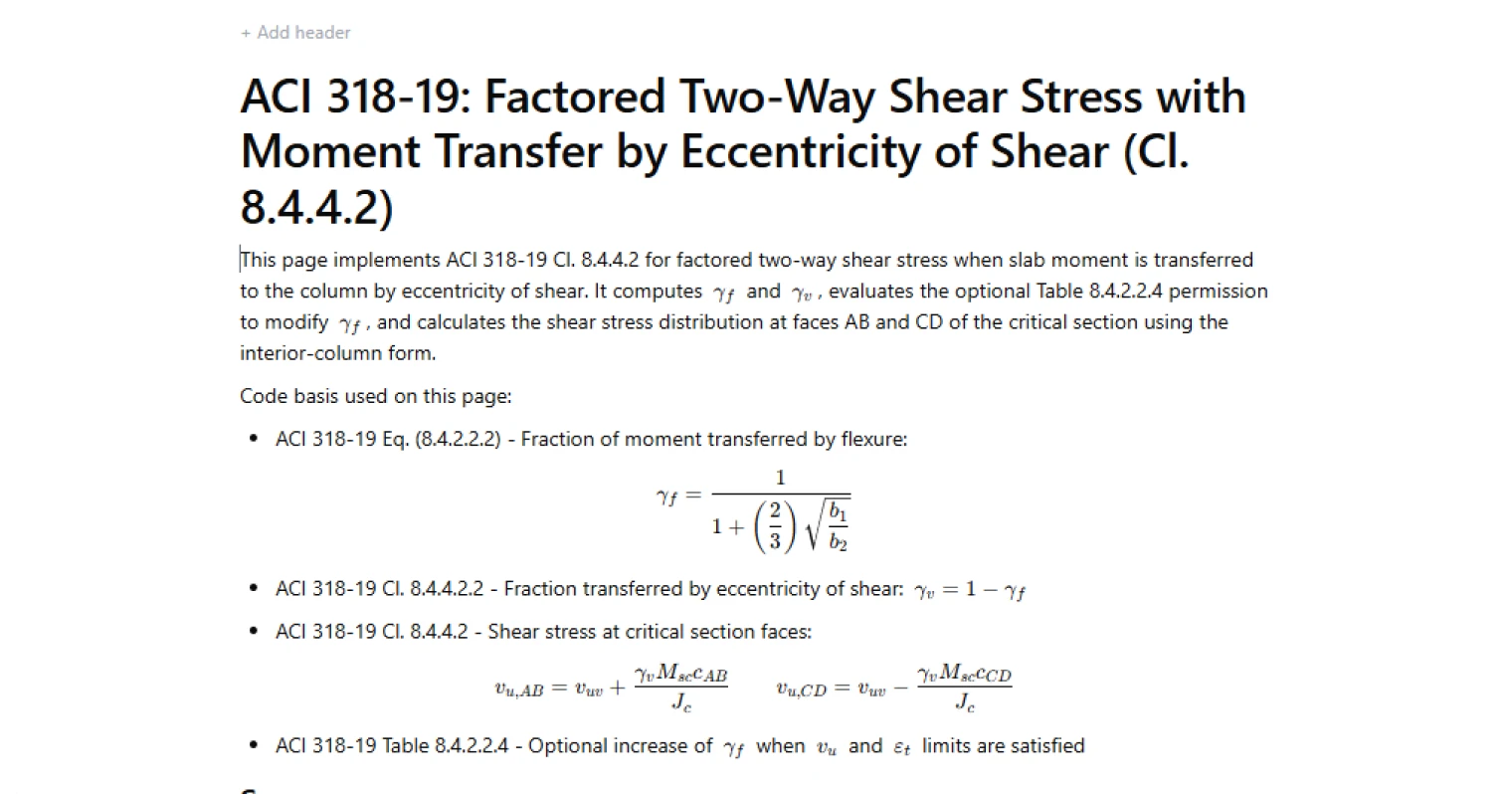
ACI 318 allows slab moment to be transferred through two mechanisms: flexure within the slab reinforcement and eccentricity of shear around the critical perimeter.
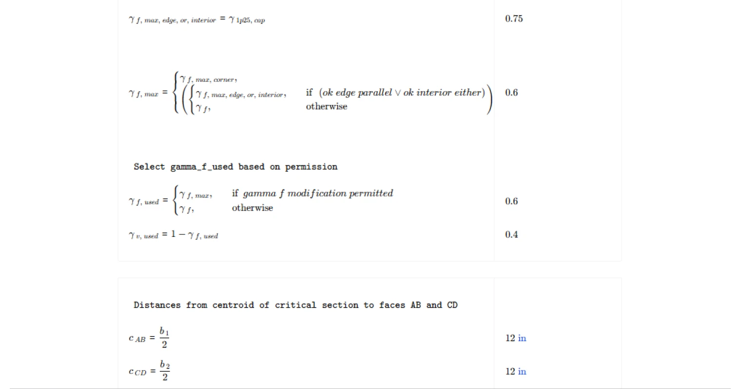
The calculator evaluates the fraction transferred by flexure using the code equation based on the geometry of the critical section. The remaining portion is automatically assigned to shear eccentricity. These fractions govern how the applied slab moment contributes to shear stress variations around the perimeter.
Table permission checks for modified flexural transfer
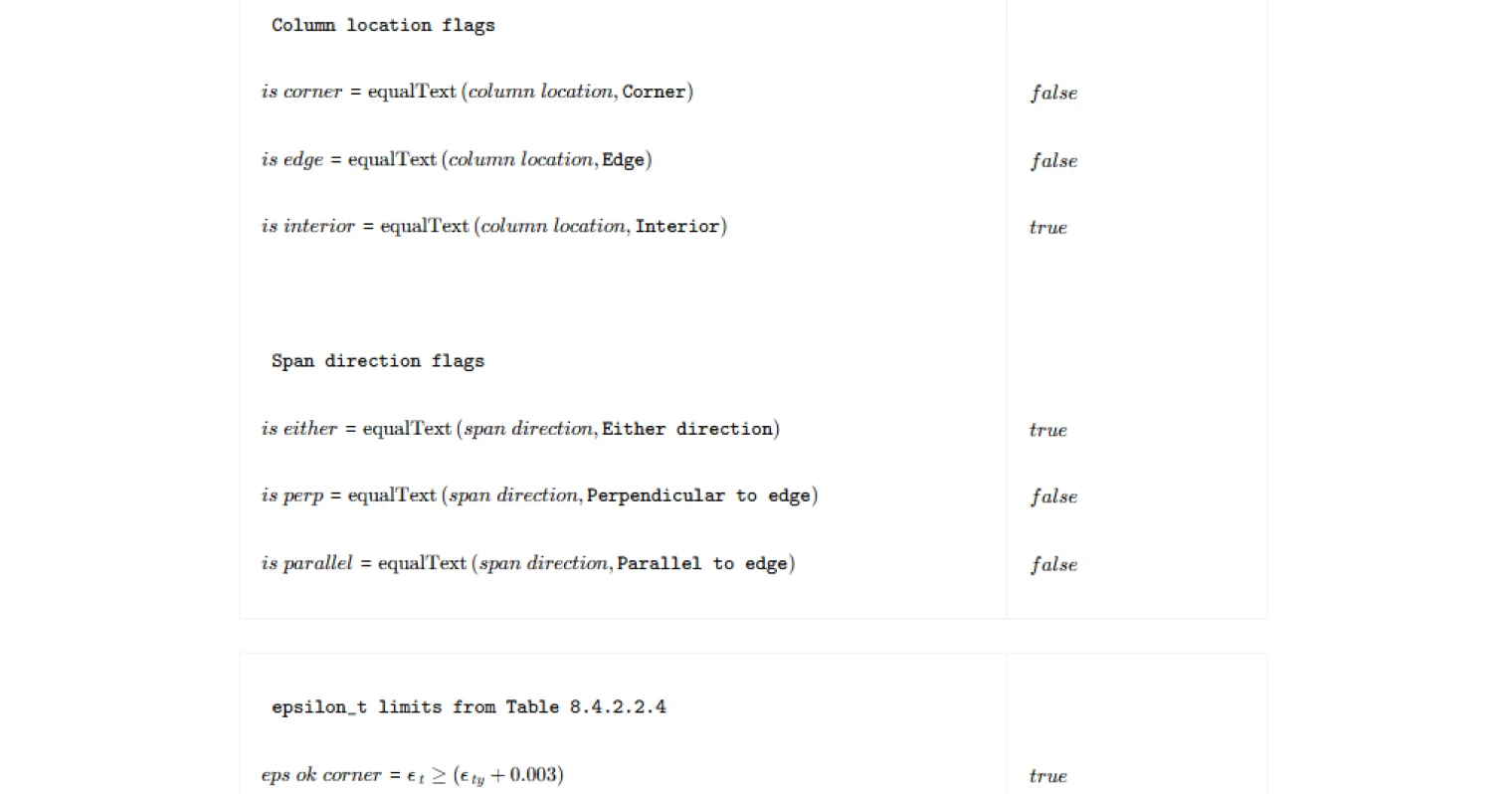
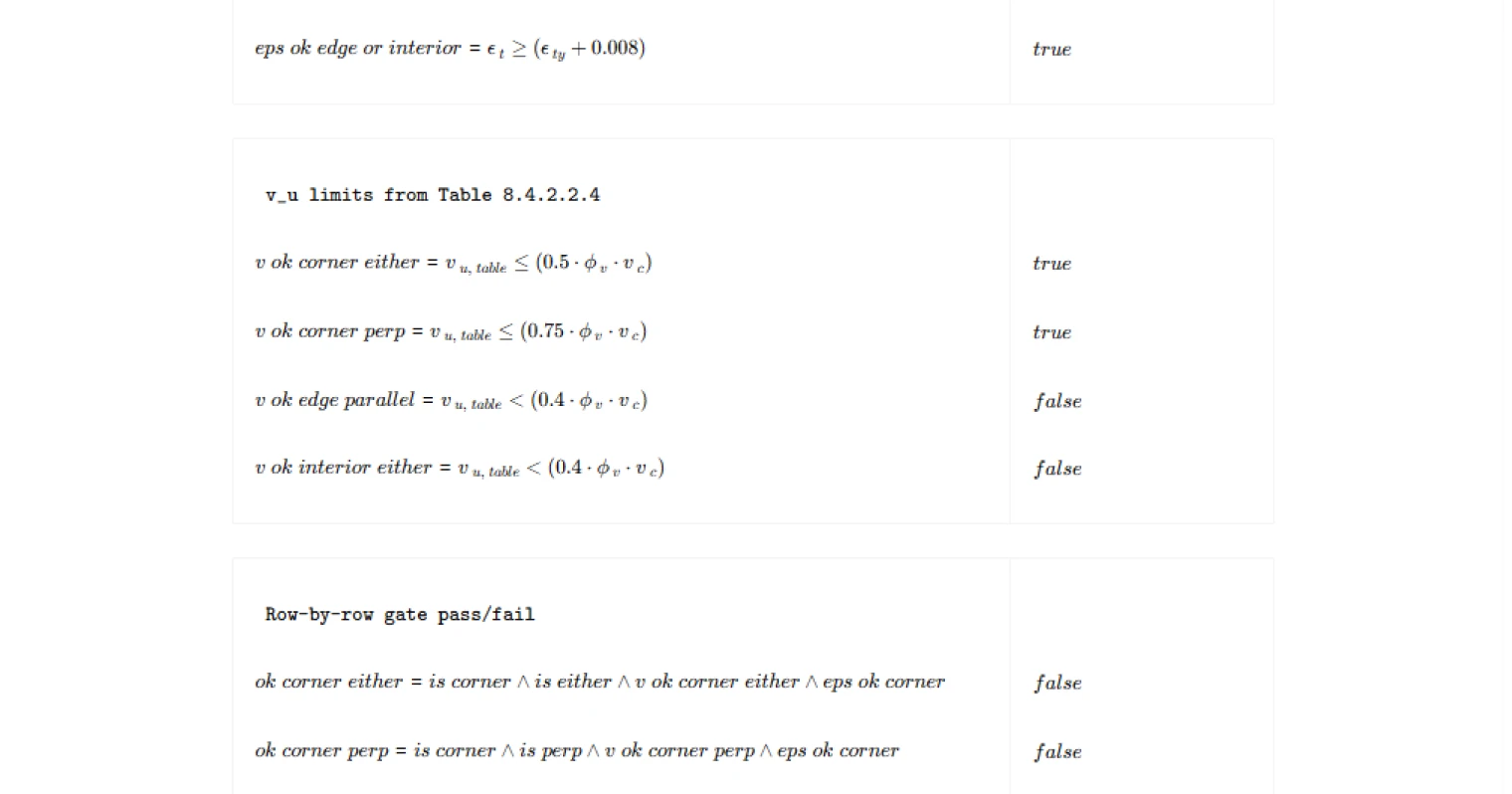
The code provides an optional allowance to increase the fraction of moment transferred by flexure when certain shear stress and strain conditions are satisfied. The calculator evaluates these gate conditions based on column location, span direction, factored shear stress, and tensile strain in the reinforcement.
If the criteria are satisfied, the flexural transfer fraction may be increased within the limits permitted by the code. The governing values are then used in the final shear stress calculation.
Shear stress distribution around the column
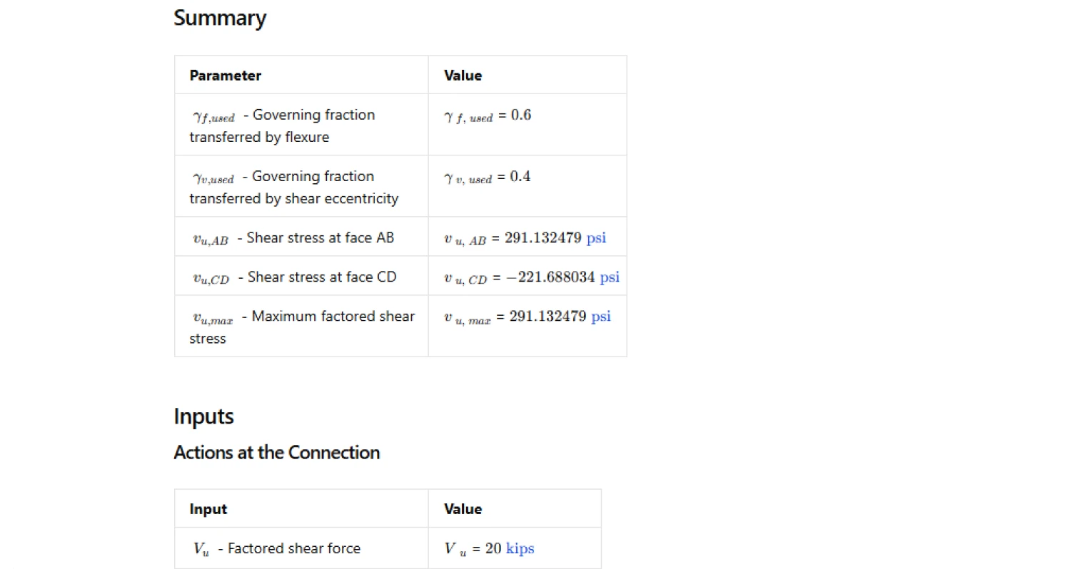
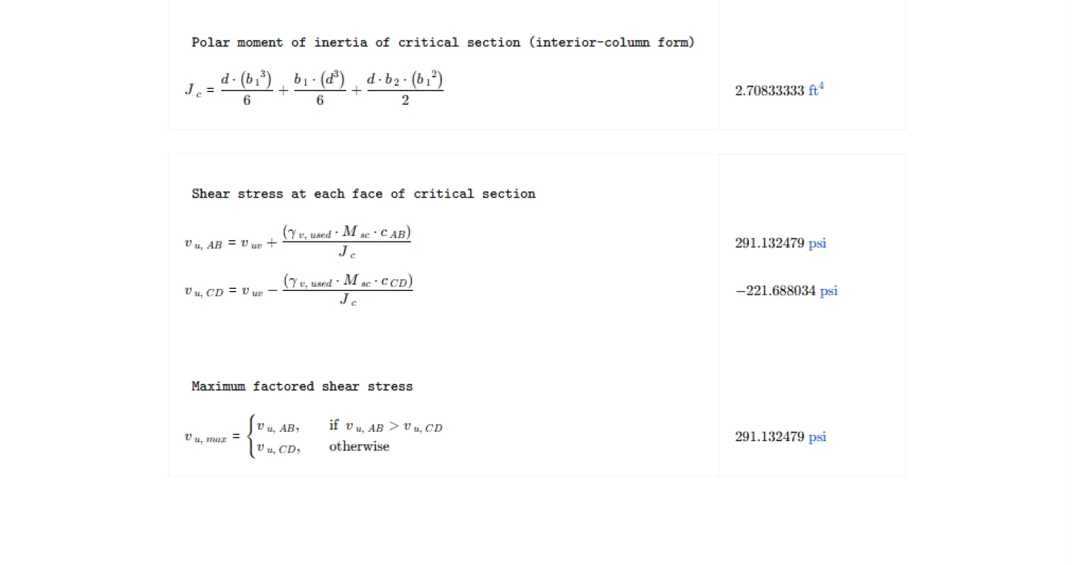
Using the governing transfer fractions, the calculator determines the shear stresses at opposite faces of the critical section caused by the combination of direct shear and moment transfer.
The polar moment of inertia of the critical section is evaluated and used to determine the additional shear stress caused by the eccentric moment. The resulting stresses are computed at each critical face, and the maximum factored shear stress is reported for design checks.
Common Calculation Errors to Avoid
- Ignoring moment transfer effects — assuming uniform shear around the critical section can underestimate shear stress when slab moments are present.
- Using incorrect column location conditions — the modification rules for moment transfer depend on whether the column is interior, edge, or corner.
- Misapplying the table permission checks — the optional increase in flexural transfer is only permitted when both shear stress and tensile strain limits are satisfied.
- Incorrect critical section geometry — errors in column dimensions or effective depth directly affect the calculated perimeter and shear stresses.
- Neglecting the governing shear face — the maximum shear stress may occur at either side of the critical section depending on the direction of moment transfer.
Engineering templates
Common calculators
Design guides
FAQs
What does ACI 318-19 Cl. 8.4.4.2 actually calculate, and why does it matter?
Two-way shear (punching shear) at slab-column connections involves not just direct shear from gravity loads but also moment transferred between the slab and column. ACI 318-19 Cl. 8.4.4.2 accounts for the portion of that moment transferred by eccentricity of shear, which produces a non-uniform stress distribution around the critical perimeter. Ignoring this uneven distribution and using only the direct shear stress can significantly underestimate peak stress at the controlling face, leading to unconservative designs.
What is the difference between γ_f and γ_v, and how are they split?
γ_f is the fraction of the unbalanced slab moment transferred to the column by flexure, calculated using ACI Eq. (8.4.2.2.2) as a function of the critical section aspect ratio b_1/b_2. γ_v is the remaining fraction transferred by eccentricity of shear, and is simply 1 − γ_f. For square columns under equal spans, γ_f ≈ 0.60 and γ_v ≈ 0.40. As the critical section becomes more rectangular, γ_f decreases and γ_v increases, meaning more moment is carried through shear eccentricity.
When does Table 8.4.2.2.4 apply, and what does it actually permit?
Table 8.4.2.2.4 allows γ_f to be increased beyond its Eq. (8.4.2.2.2) baseline value, which reduces γ_v and lowers the computed shear stress. This is only permitted when both a shear stress limit (v_u ≤ some fraction of φ_v·v_c) and a ductility limit (ε_t sufficiently above yield strain) are satisfied. The limits differ depending on column location and span direction. For interior columns in either span direction, the shear stress must be below 0.4φ_v·v_c and ε_t ≥ ε_ty + 0.008. If those gates pass, γ_f can be increased up to min(1.25γ_f, 1.0). This template evaluates all applicable table rows automatically and flags whether the modification is permitted.
Why are shear stresses calculated at faces AB and CD separately?
The eccentricity of shear creates a moment about the centroid of the critical section. Face AB is on the side where that moment adds to the direct shear stress, and face CD is on the opposite side where it subtracts. For an interior column, c_AB = c_CD = b_1/2 by symmetry. The governing design stress is the larger of the two, taken as v_u,max. Checking both faces is important because, depending on the sign of M_sc, either face could control if you are looking at multiple load combinations.
What inputs does this template need that are not already from the structural analysis?
Beyond the factored actions V_u and M_sc from your load combinations, you need the column dimensions c_1 and c_2, effective slab depth d, and the concrete shear capacity v_c with φ_v if you want to evaluate the Table 8.4.2.2.4 permission. You also need the net tensile strain ε_t at the extreme tension steel, which comes from your flexural design of the slab strip framing into the connection. The column location and span direction selectors control which row of Table 8.4.2.2.4 is checked, so set those to match your actual floor layout.
Does this calculation check punching shear capacity, or just compute demand?
This template computes factored shear stress demand only. It outputs v_u,AB, v_u,CD, and v_u,max at the critical section faces. You need to separately evaluate the available shear stress capacity φ_v·v_n per ACI 318-19 Cl. 22.6 and compare it against v_u,max to confirm the section is adequate. Keeping demand and capacity as separate steps makes it easier to audit each part of the check independently.
Learn about the benefits of using CalcTree on engineering projects!