Calculate two-way shear strength vc per ACI 318-19 §22.6.5 for non-prestressed and prestressed slabs. Covers Tables 22.6.5.2 & 22.6.5.5. Try it free.

This template is not available yet. You can sign up and create it yourself!
Or let us know if you'd like to be notified when it’s ready:


No items found.
No items found.
About this ACI 318 Two-Way Shear Strength (v_c) Calculator
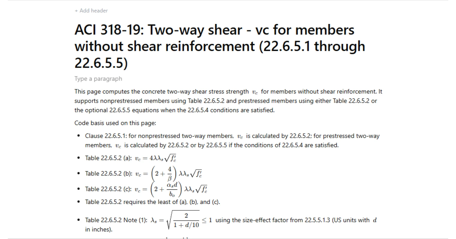
This calculator determines the concrete two-way shear stress strength (v_c) for slab–column regions and similar members without shear reinforcement using ACI 318 provisions. It evaluates the applicable equations from Table 22.6.5.2 and, for prestressed members, optionally applies the alternative equations of Clause 22.6.5.5 when the conditions of Clause 22.6.5.4 are satisfied.
- Structural engineer — evaluate punching shear capacity at slab–column connections and verify compliance with ACI 318 provisions.
- Bridge or building designer — compare different column geometries, prestress effects, and slab depths to understand their influence on two-way shear strength.
- Engineering reviewer — verify the governing equation and confirm that the correct code pathway has been applied for prestressed or nonprestressed members.
All governing equations, limits, and conditional logic from ACI 318 are implemented transparently so the resulting (v_c) value can be traced back to the relevant clause. This is an engineering-grade calculator built for rigorous and auditable structural calculations in CalcTree.
More info on ACI 318 Two-Way Shear Strength (v_c)
Inputs
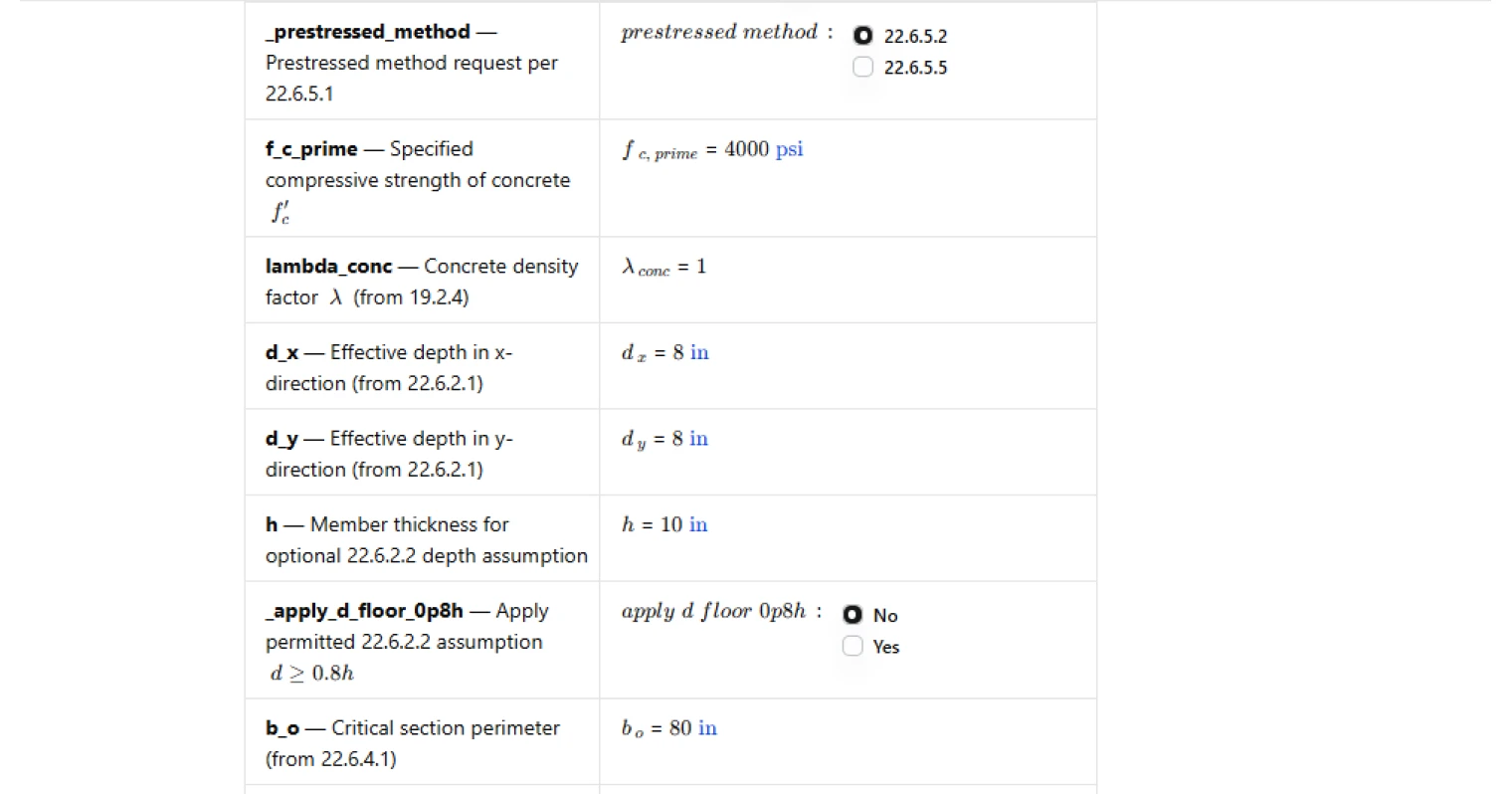
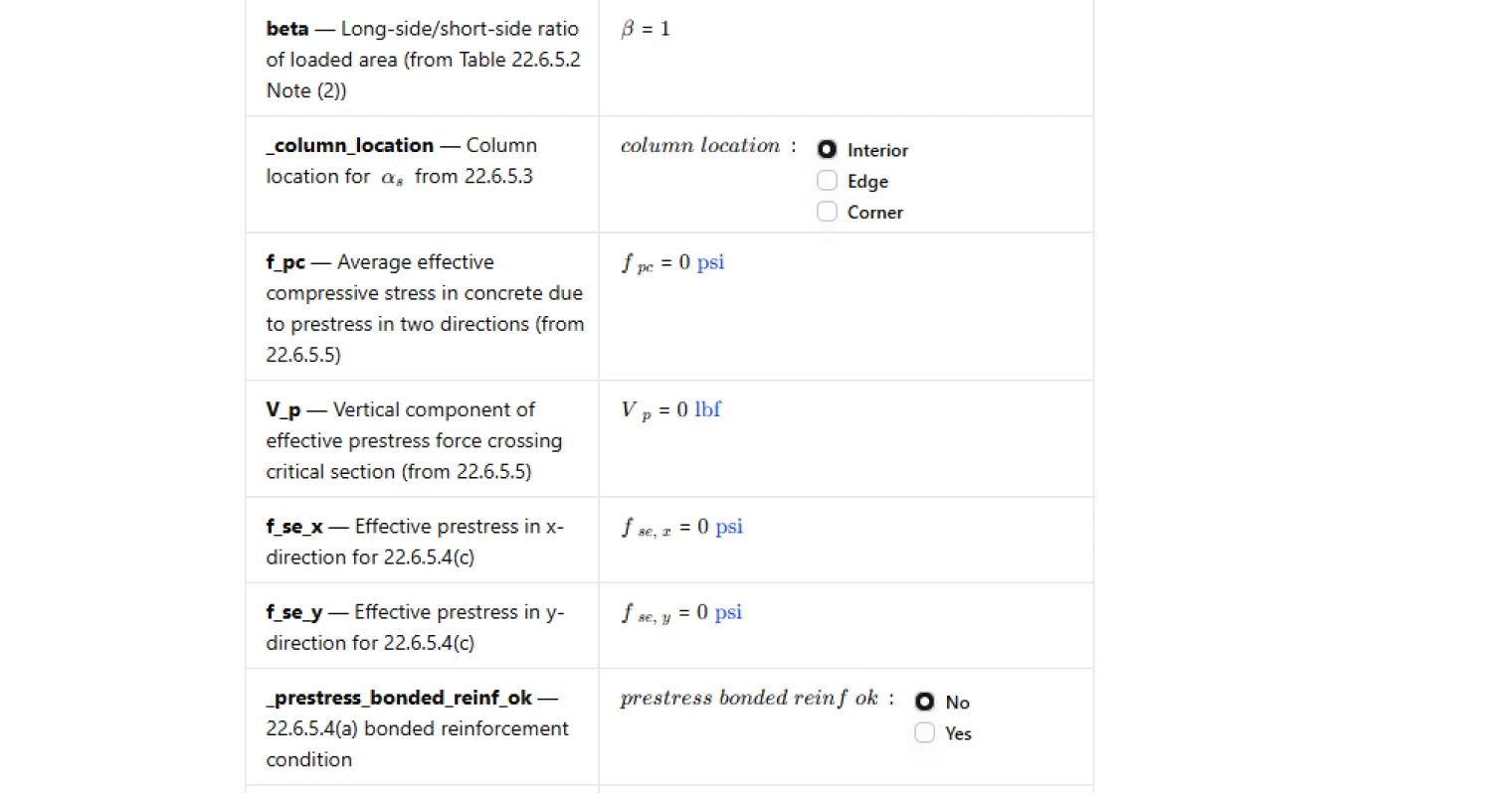
The calculator requires material properties, geometry, and classification parameters that affect two-way shear resistance. These include the specified concrete compressive strength, concrete density factor, effective depths in two orthogonal directions, slab thickness, and the critical section perimeter around the column or loaded area.
Additional inputs define the geometry of the loaded region and column location, which determine parameters such as the column aspect ratio and the coefficient associated with interior, edge, or corner columns. For prestressed members, inputs describing the effective prestress, vertical prestress force crossing the critical section, and reinforcement conditions are also required.
Effective depth and size-effect factor
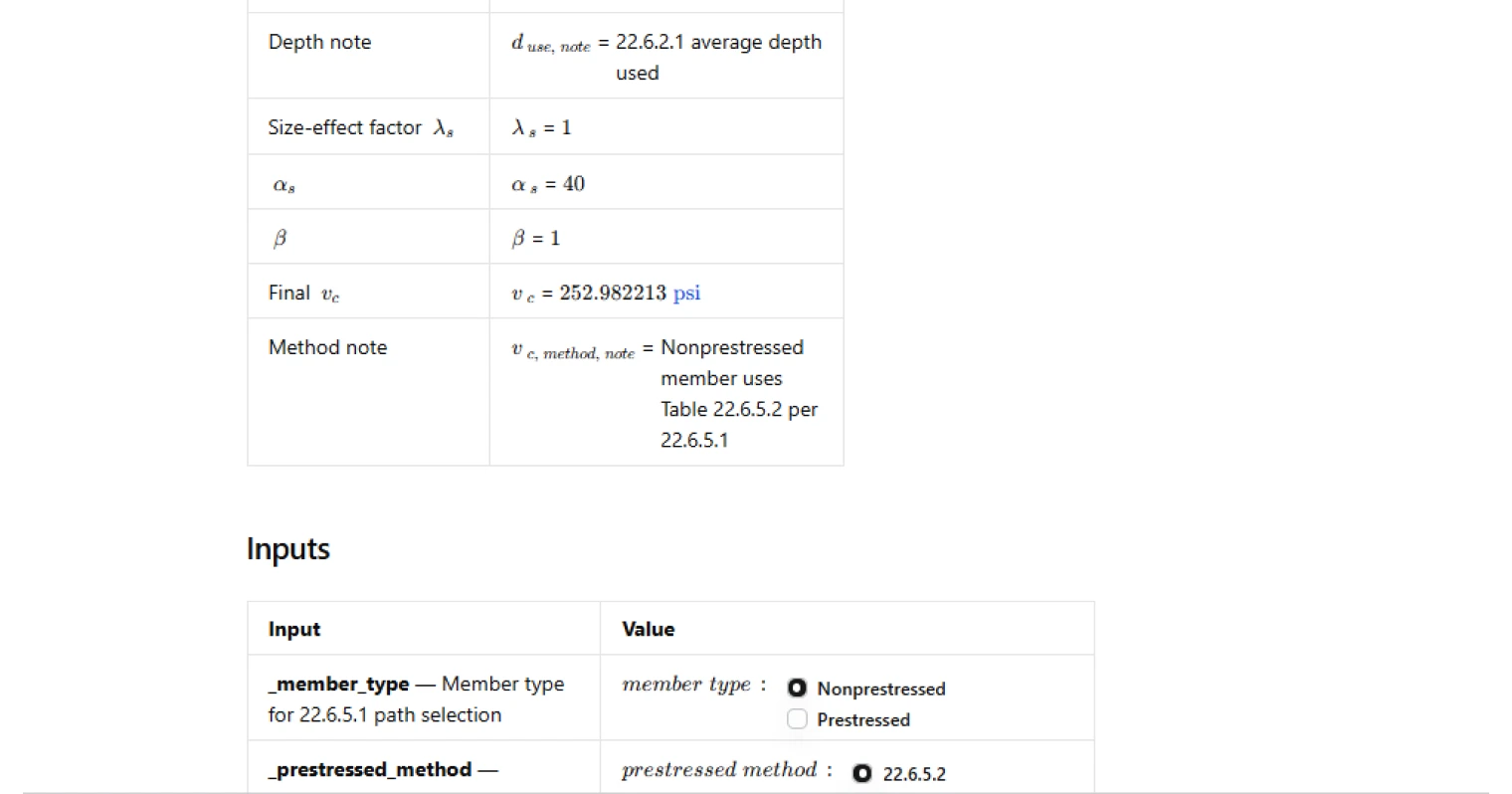
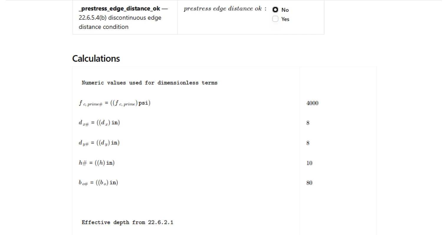
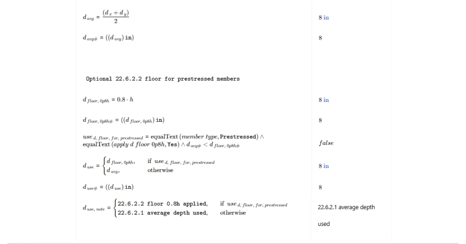
The effective depth used in the calculation is determined as the average of the effective depths in the two orthogonal directions in accordance with ACI 318 two-way shear provisions. For prestressed members, the code allows an optional lower bound related to the member thickness, which the calculator can apply when permitted.
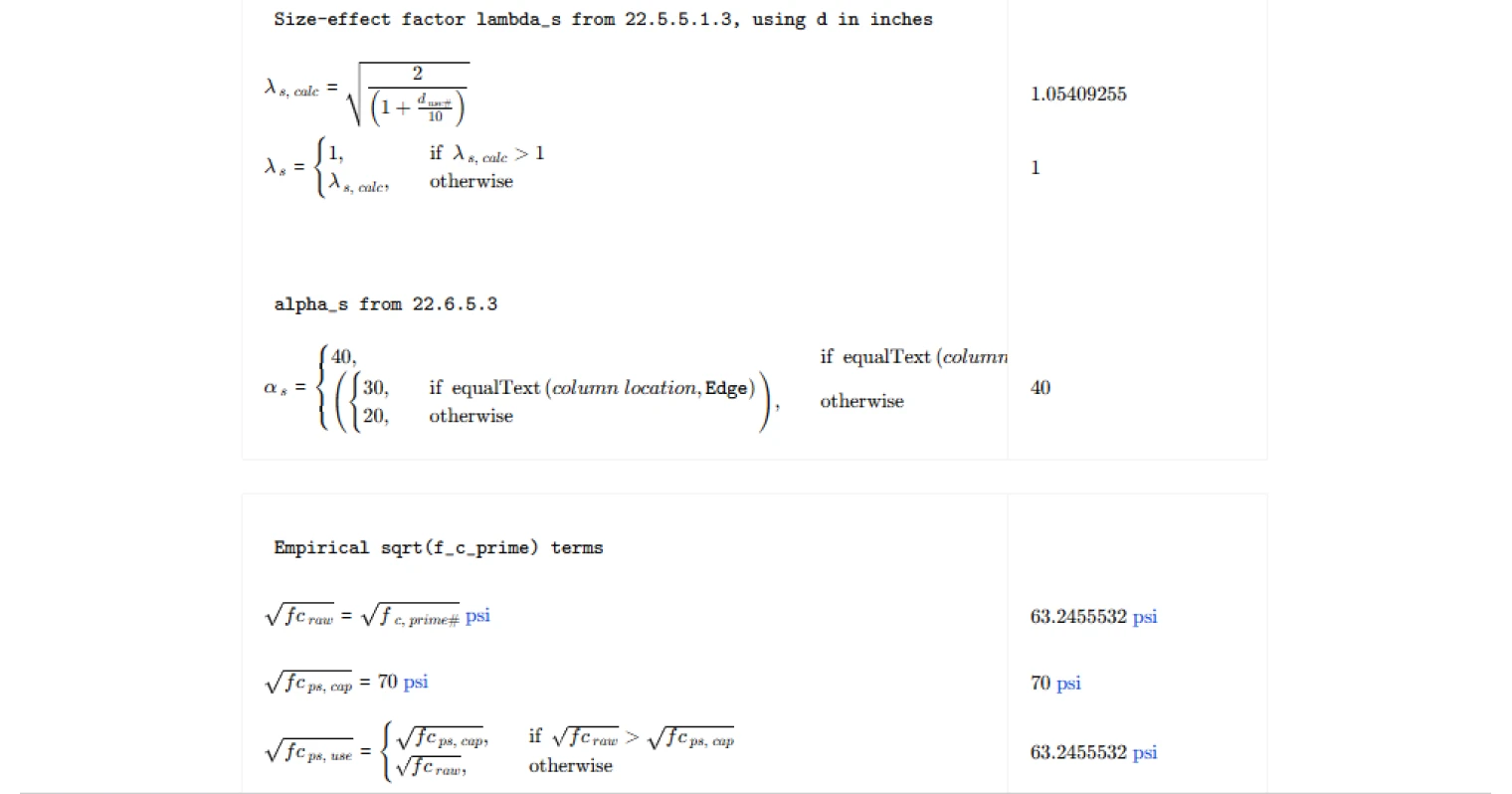
Using this effective depth, the calculator computes the size-effect factor defined in the shear provisions. This factor modifies the nominal concrete shear stress capacity to reflect the influence of member depth on shear behavior.
Nominal two-way shear strength equations
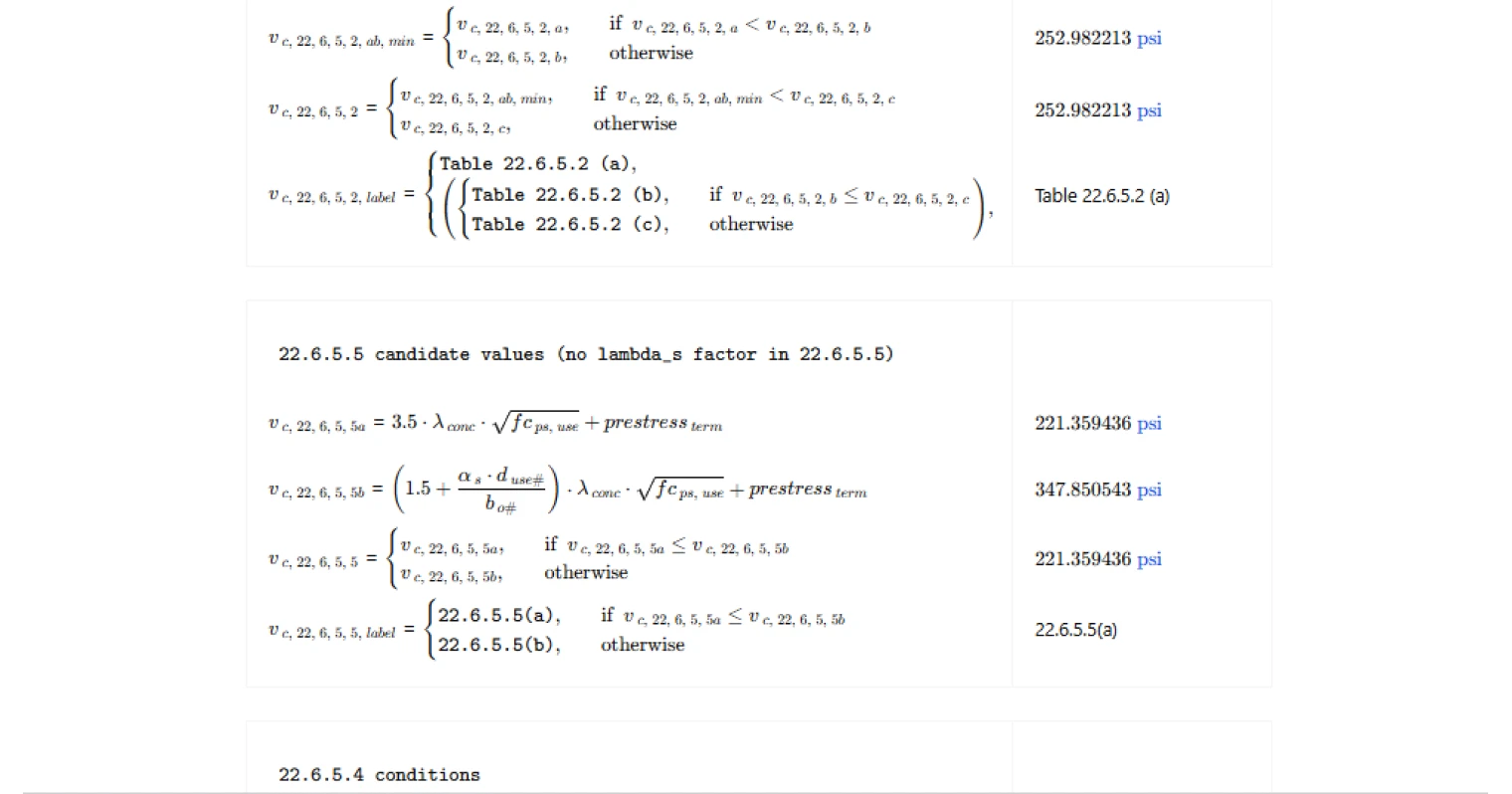
For nonprestressed members, the calculator evaluates the three candidate expressions provided in ACI 318 Table 22.6.5.2. These expressions account for concrete strength, the size-effect factor, column aspect ratio, and column location. The governing value of (v_c) is taken as the least of the candidate equations, as required by the code.
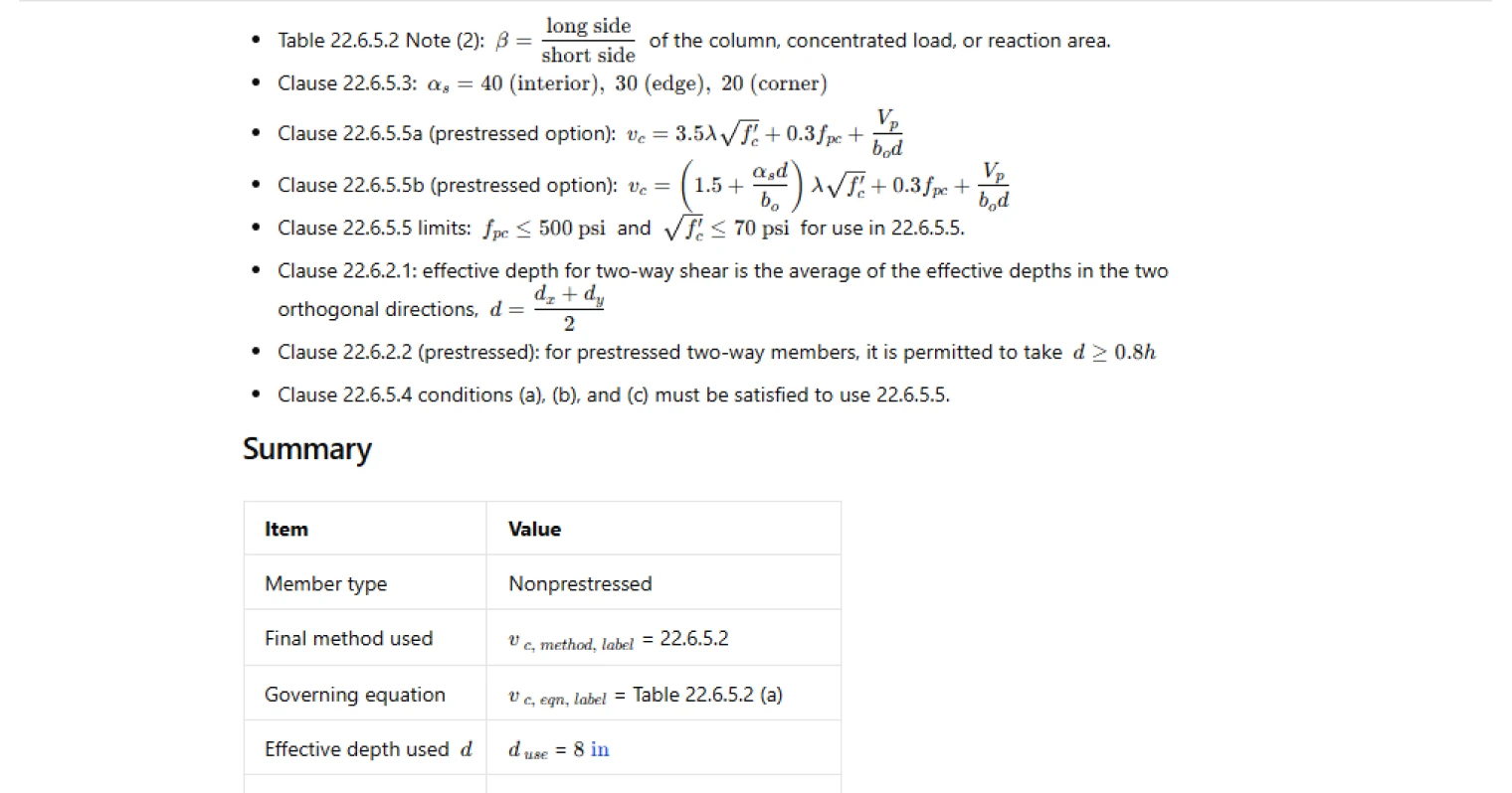
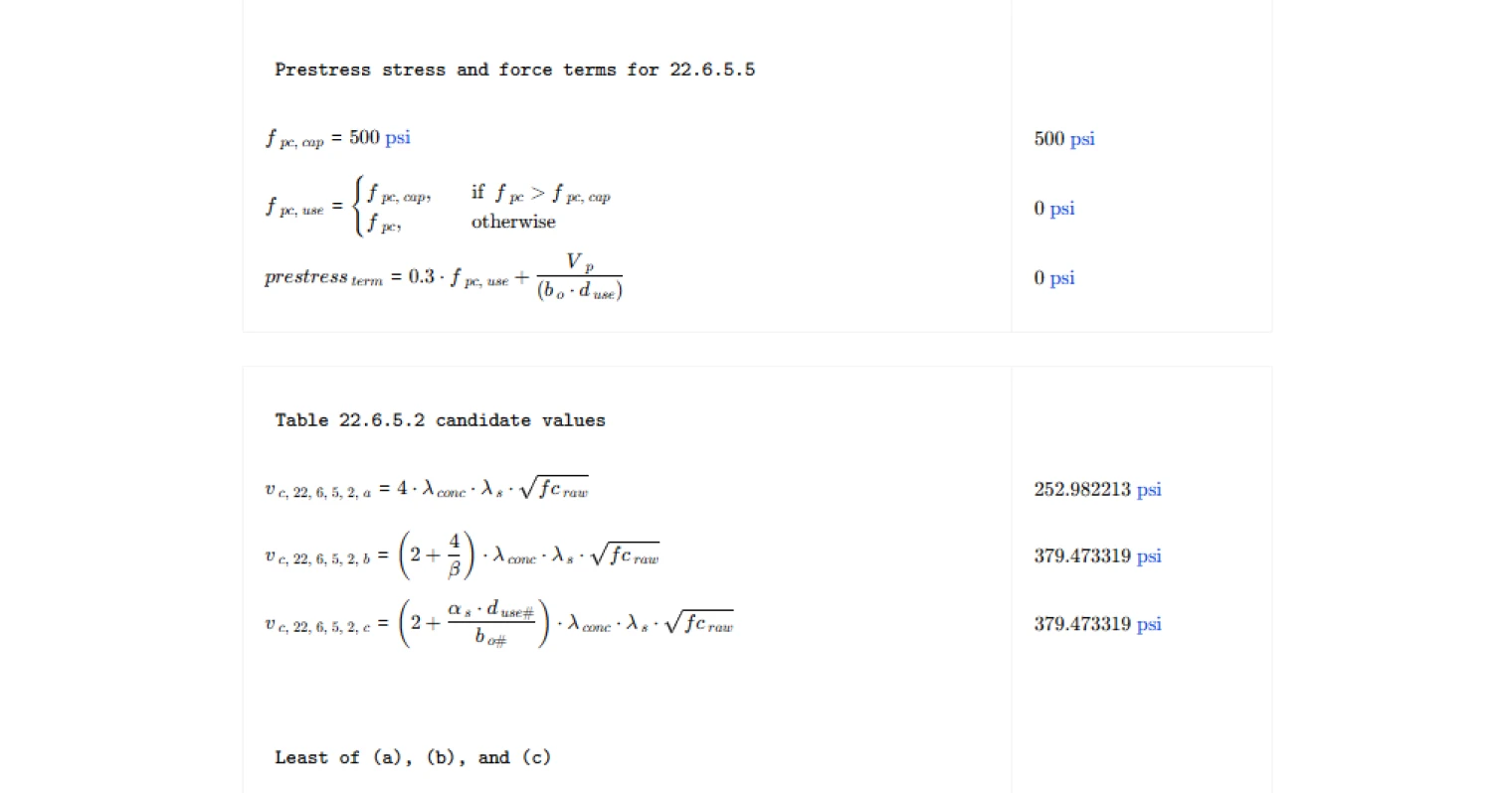
For prestressed members, the same Table 22.6.5.2 equations may be used. Alternatively, the calculator can apply the equations in Clause 22.6.5.5, which incorporate prestress effects through additional stress and force terms. These equations consider the effective prestress in the concrete and the vertical component of prestress crossing the critical section.
Method selection and applicability checks
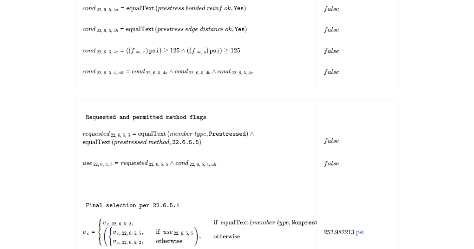
The final calculation pathway depends on whether the member is prestressed or nonprestressed. Nonprestressed members automatically use the Table 22.6.5.2 equations. Prestressed members may use either Table 22.6.5.2 or the alternative equations of Clause 22.6.5.5.
Before applying the prestressed equations, the calculator verifies the applicability conditions specified in the code. These include requirements related to bonded reinforcement, edge distance conditions, and minimum effective prestress in each direction. If these conditions are not satisfied, the calculator automatically falls back to the Table 22.6.5.2 method.
Common Calculation Errors to Avoid
- Incorrect column aspect ratio definition — The parameter representing the ratio of long side to short side of the loaded area must be defined correctly. Reversing the ratio can lead to unconservative results.
- Using the prestressed equations when conditions are not satisfied — The alternative prestressed shear equations are permitted only when the specific applicability conditions are met. Ignoring these checks can invalidate the design.
- Ignoring effective depth requirements — The effective depth used in two-way shear calculations must follow the averaging rule defined in the code and any permitted minimum limits for prestressed members.
- Overlooking code limits on prestress parameters — Certain parameters used in the prestressed equations have upper bounds defined by the code. These limits must be enforced to avoid overstating the shear strength.
- Using the wrong column location coefficient — Interior, edge, and corner columns use different coefficients in the shear stress equation. Selecting the wrong case will change the resulting shear capacity.
Engineering templates
Common calculators
Design guides
FAQs
What does this calculation actually produce, and where does it fit in a punching shear check?
This page computes the nominal concrete shear stress strength vc for two-way (punching) shear at a column or concentrated load, for members without shear reinforcement, per ACI 318-19. The result is a stress in psi, not a force. To complete the punching shear check, compare phi * vc against the factored shear stress vu = Vu / (bo * d) at the critical perimeter. This page covers only the vc side of that comparison.
Why does Table 22.6.5.2 give three candidate equations, and which one governs?
The three equations each capture a different potential failure mode or geometric effect. Equation (a) is the baseline capacity. Equation (b) reduces capacity when the loaded area is elongated (large beta), because punching failure becomes more like one-way shear along the long sides. Equation (c) reduces capacity for large critical perimeters relative to slab depth, which occurs at edge and corner columns. ACI requires you take the least of the three, so all three are computed and the minimum governs. The calculation reports which equation controls.
What is the size-effect factor lambda_s, and when does it reduce vc?
Lambda_s accounts for the reduced shear efficiency of thicker slabs, introduced in ACI 318-19. It is calculated as sqrt(2 / (1 + d/10)) with d in inches, capped at 1.0. For shallow slabs with d at or below roughly 10 inches, lambda_s equals 1.0 and has no effect. For deeper slabs, it drops below 1.0 and reduces vc. This factor only applies to Table 22.6.5.2; the prestressed 22.6.5.5 equations do not include lambda_s.
When can I use the 22.6.5.5 equations for a prestressed slab, and what are the three conditions?
The 22.6.5.5 equations are an alternative available only for prestressed members when all three conditions of 22.6.5.4 are satisfied. Condition (a) requires that bonded reinforcement is provided through the column cage in each direction. Condition (b) requires adequate distance from the column to any discontinuous slab edge. Condition (c) requires effective prestress fse of at least 125 psi in each direction. If any condition fails, the calculation automatically falls back to Table 22.6.5.2, and the method note in the summary table explains why.
How do I enter bo, beta, and column location, and where do those values come from?
These three inputs must be determined by the engineer before using this page. bo is the critical section perimeter from ACI 22.6.4, located at d/2 from the column face; compute it separately for your column geometry. Beta is the ratio of the long side to the short side of the column or loaded area, always entered as a value of 1.0 or greater. Column location sets alpha_s to 40 for interior, 30 for edge, or 20 for corner columns per 22.6.5.3. Getting these right is critical because they directly influence which Table 22.6.5.2 equation governs.
What happens if my prestressed slab has fpc above 500 psi or sqrt(f'c) above 70 psi when using 22.6.5.5?
ACI 318-19 clause 22.6.5.5 places explicit upper limits on both terms. If fpc exceeds 500 psi, the calculation caps it at 500 psi in the equation. If sqrt(f'c) exceeds 70 psi (equivalent to f'c above 4,900 psi), the calculation caps sqrt(f'c) at 70 psi. Both caps are flagged in the checks table. The calculation still runs and produces a valid vc, but you should note that the actual material properties exceed the range tested for those equations.
Learn about the benefits of using CalcTree on engineering projects!