Check ACI 318-19 slenderness neglect criteria and second-order moment limits for sway and nonsway frames. Run the free CalcTree template now.

This template is not available yet. You can sign up and create it yourself!
Or let us know if you'd like to be notified when it’s ready:
No items found.
No items found.
About this ACI 318-19: Slenderness Effects — Neglect Criteria and Second-Order Moment Limit (Cl. 6.2.5) Calculator
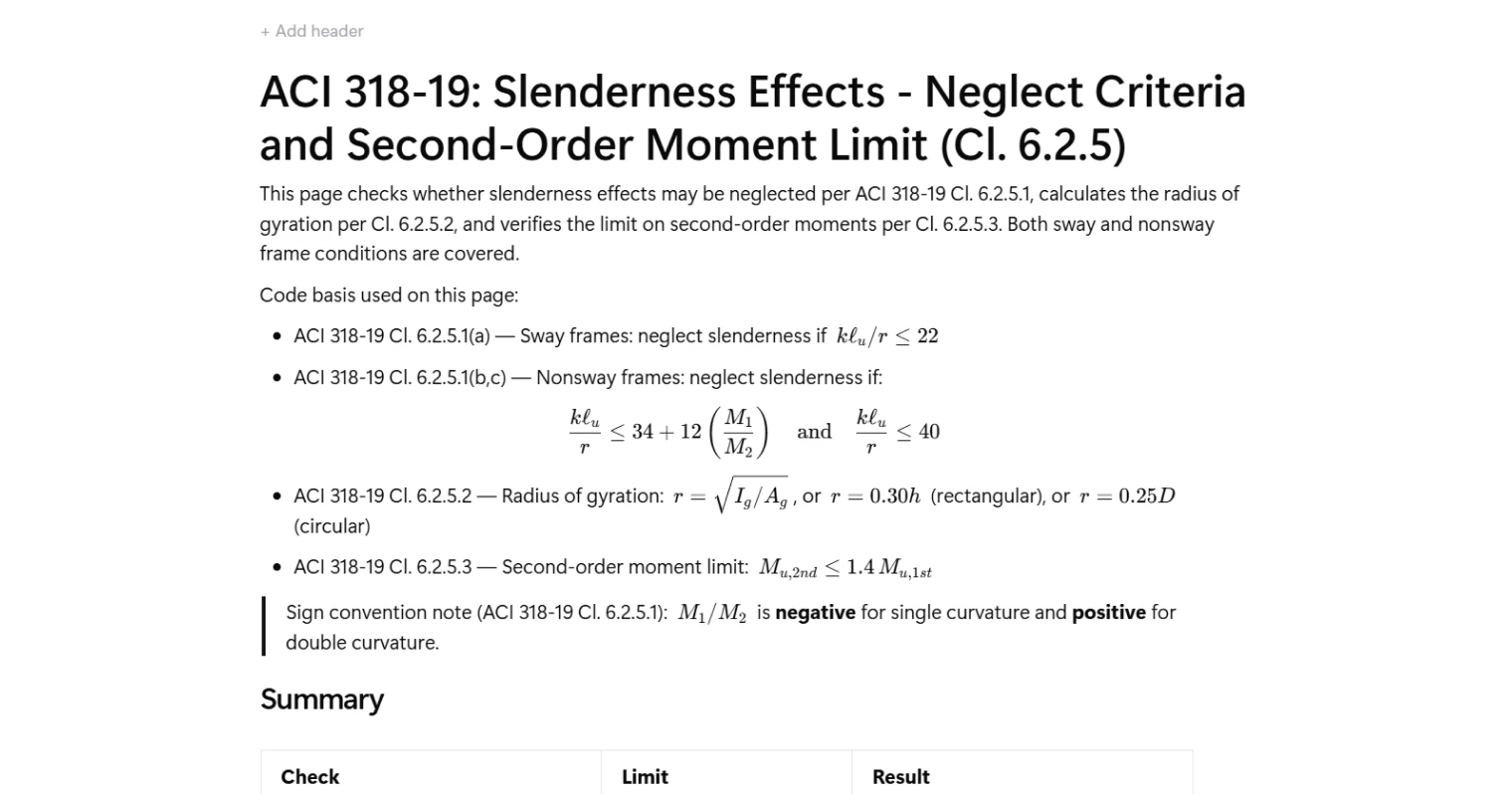
This calculator checks whether slenderness effects may be neglected for a concrete compression member per ACI 318-19 Cl. 6.2.5.1, computes the radius of gyration per Cl. 6.2.5.2, and verifies that second-order moments do not exceed the amplification limit set out in Cl. 6.2.5.3. It covers both sway and nonsway frame conditions and applies the correct slenderness limits for each case.
- Structural engineer — run the slenderness neglect check for columns in braced or unbraced frames and confirm whether a simplified first-order analysis is sufficient before proceeding to magnified moment design.
- Project engineer — verify that second-order moment amplification stays within the ACI 318-19 limit as part of a column design package, with all intermediate values visible for review and sign-off.
- Design checker — audit slenderness classifications, radius of gyration method selection, and moment ratio sign conventions against the code in a single traceable page.
This is an engineering-grade calculator built on CalcTree, where every intermediate result is shown and the calculation can be saved, shared, and linked to a wider column or frame design workflow.
More Info on ACI 318-19: Slenderness Effects — Neglect Criteria and Second-Order Moment Limit (Cl. 6.2.5)
Inputs
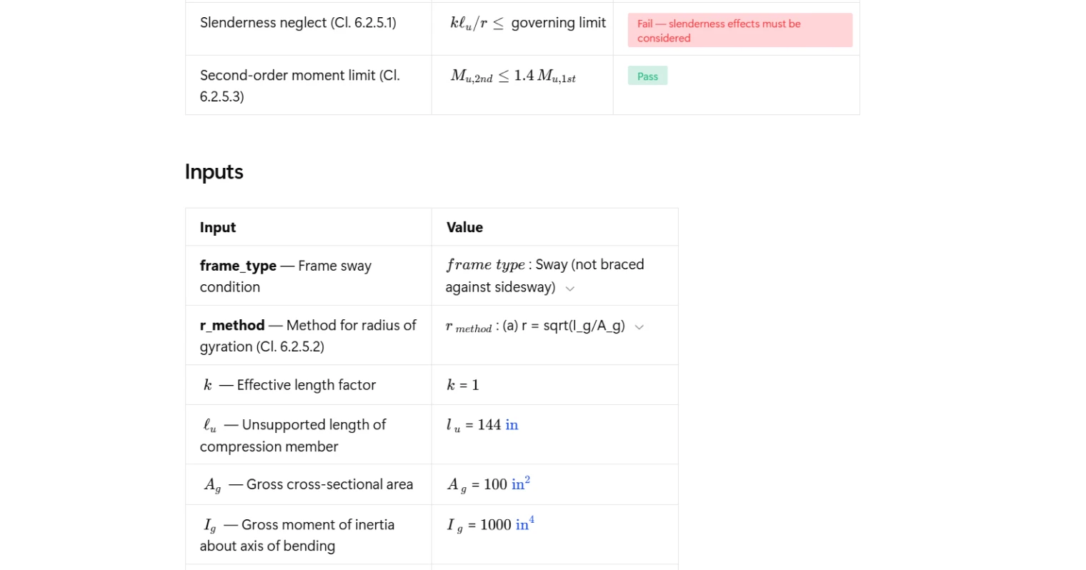
The calculator takes geometric, section, and loading inputs for a single compression member. The frame sway condition is selected first, as it determines which slenderness limit applies. The effective length factor and unsupported length define the member's slenderness. Cross-section properties — gross area, gross moment of inertia, overall depth for rectangular sections, or diameter for circular sections — feed into the radius of gyration calculation, with the method selected by the user per Cl. 6.2.5.2.
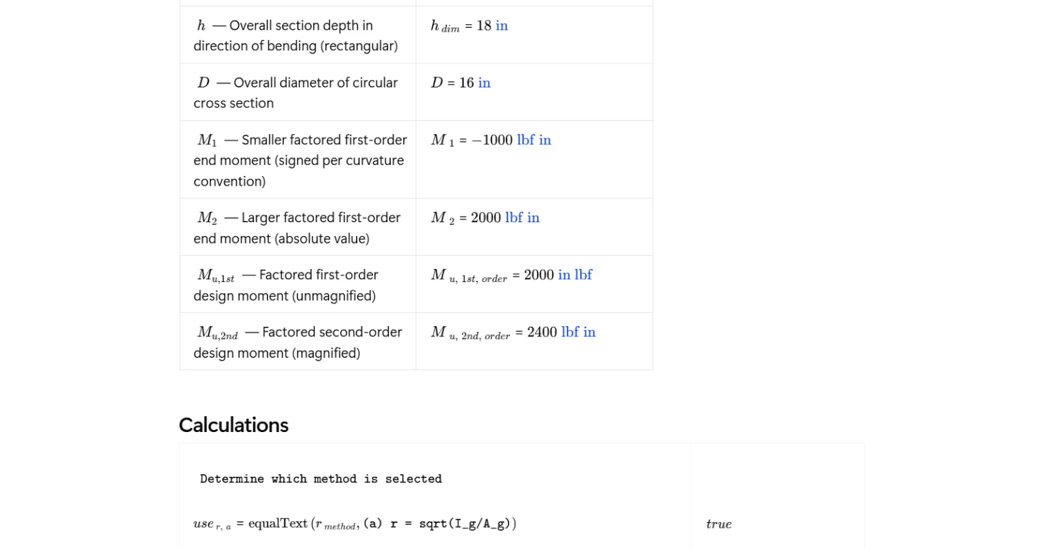
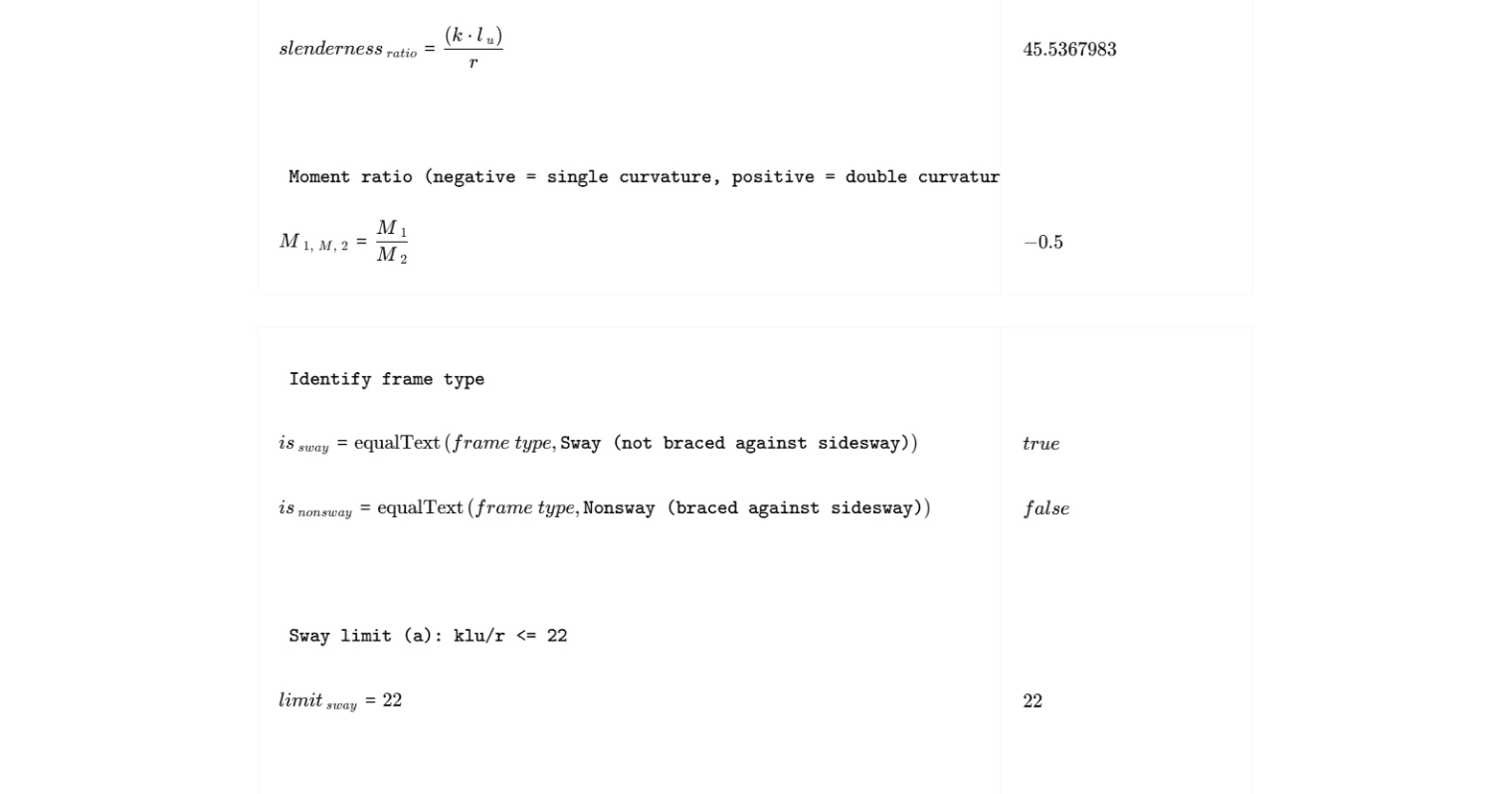
For the slenderness neglect check, the smaller and larger factored first-order end moments are entered with the sign convention from Cl. 6.2.5.1: the ratio M1/M2 is negative for single curvature and positive for double curvature. For the second-order moment limit check, the factored first-order and second-order design moments are entered separately so the amplification ratio can be computed directly.
Radius of Gyration
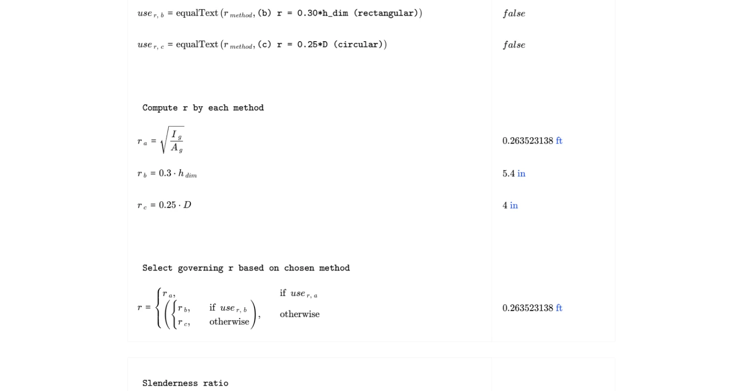
The radius of gyration is calculated per Cl. 6.2.5.2 using one of three methods, selected by the user. The general method derives it from the gross moment of inertia divided by the gross cross-sectional area, taken under a square root. The two simplified methods apply section-specific multipliers: a factor of 0.30 times the overall section depth for rectangular members, or 0.25 times the overall diameter for circular members. The selected method feeds directly into the slenderness ratio calculation.
Slenderness Neglect Check — Cl. 6.2.5.1
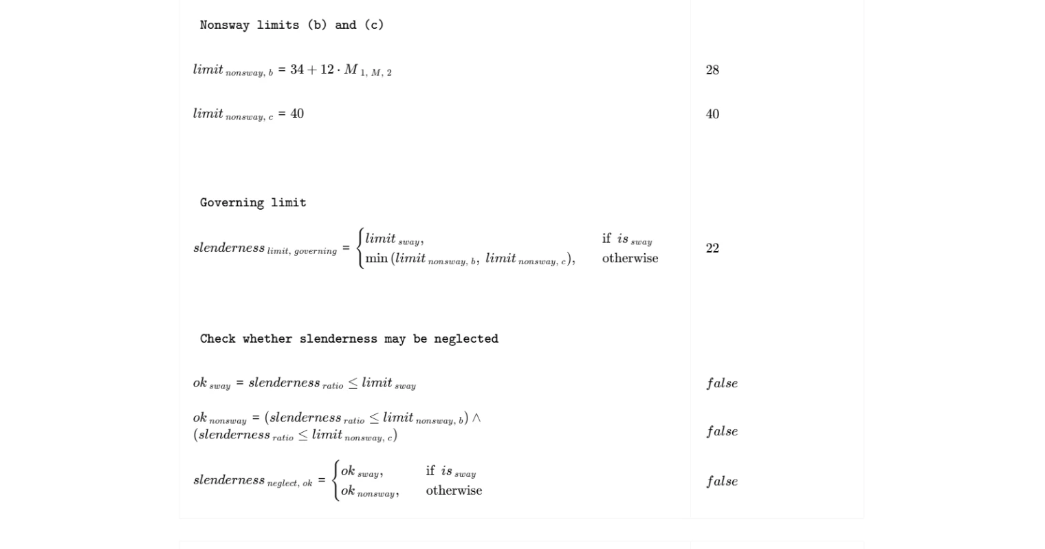
The slenderness ratio is computed as the product of the effective length factor and the unsupported length, divided by the radius of gyration. For sway frames, slenderness may be neglected if this ratio does not exceed 22, per Cl. 6.2.5.1(a). For nonsway frames, two limits apply concurrently per Cl. 6.2.5.1(b) and (c): a moment-ratio-dependent limit of 34 plus 12 times M1/M2, and an absolute cap of 40. The calculator evaluates the governing limit for the selected frame type and checks the slenderness ratio against it, returning a pass or fail result.
Second-Order Moment Limit — Cl. 6.2.5.3
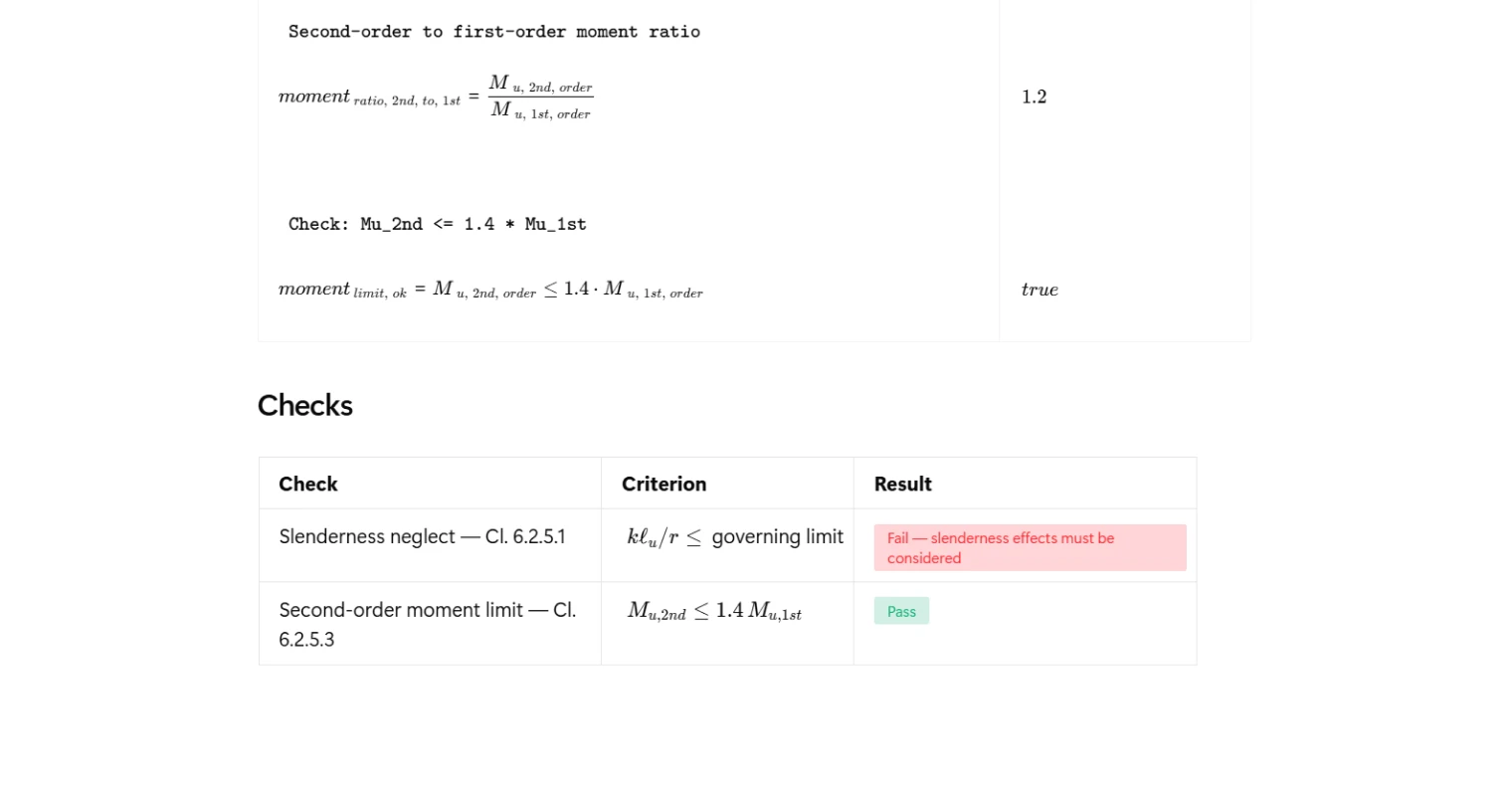
Per Cl. 6.2.5.3, the factored second-order moment must not exceed 1.4 times the factored first-order moment. If this limit is exceeded, the analysis method being used is considered unreliable and a more rigorous approach is required. The calculator computes the ratio of second-order to first-order moment and checks it against this limit independently of the slenderness neglect check, so both conditions are reported clearly in the summary.
Common Calculation Errors to Avoid
- Applying the wrong slenderness limit for the frame type — the limit of 22 applies only to sway frames; using it for a nonsway frame is unconservative. Confirm the lateral bracing condition before selecting the frame type.
- Getting the M1/M2 sign wrong — ACI 318-19 Cl. 6.2.5.1 requires M1/M2 to be negative for single curvature and positive for double curvature. Entering the ratio as a positive value when the column bends in single curvature will overstate the nonsway neglect limit.
- Using M2 equal to zero — a zero or near-zero larger end moment causes a division error or an unrealistic moment ratio. If end moments are negligible, review whether a minimum eccentricity or moment should be applied per the broader ACI 318-19 column design requirements.
- Selecting the wrong radius of gyration method — using the simplified rectangular or circular approximations for non-standard sections can introduce error. The general method using the gross section properties is always applicable and should be preferred when section geometry is irregular.
- Confusing first-order and second-order moments in the amplification check — the Cl. 6.2.5.3 check compares the magnified second-order moment to the unmagnified first-order moment. Substituting already-amplified values into both sides of the ratio will produce a misleading result.
- Overlooking the absolute cap of 40 for nonsway frames — the nonsway limit from Cl. 6.2.5.1(b) can exceed 40 for double-curvature bending with a favorable moment ratio, but Cl. 6.2.5.1(c) caps the limit regardless. Both limits must be satisfied simultaneously.
Engineering templates
Common calculators
Design guides
FAQs
What does it mean to "neglect slenderness effects" under ACI 318-19?
ACI 318-19 Cl. 6.2.5.1 allows you to skip the more involved moment magnification procedure if the slenderness ratio klu/r falls below a code-specified threshold. Below that limit, second-order effects are small enough that they can be ignored without materially affecting design accuracy. For sway frames the limit is a fixed 22. For nonsway frames it ranges up to 40 depending on the end moment ratio M1/M2, with more favorable limits when the column bends in double curvature.
What is the sign convention for M1/M2 in this calculation?
Per ACI 318-19 Cl. 6.2.5.1, M1/M2 is negative for single curvature (moments cause the column to bow in one direction) and positive for double curvature (moments at opposite ends reverse the bending shape). This matters directly for nonsway frames because the nonsway limit is 34 + 12(M1/M2), so a column in double curvature gets a higher threshold and is more likely to qualify for neglecting slenderness. Enter M1 with the appropriate sign and enter M2 as the absolute larger end moment.
Which radius of gyration method should I select?
The calculation offers three options per Cl. 6.2.5.2. Option (a), r = sqrt(Ig/Ag), is exact for any cross-section shape and should be used when you have both Ig and Ag readily available. Option (b), r = 0.30h, is a convenient shortcut for rectangular sections. Option (c), r = 0.25D, applies to circular sections. For non-standard shapes, stick with option (a) to avoid approximation error.
What happens if the slenderness check fails?
A fail result means slenderness effects cannot be neglected and you must account for second-order behavior explicitly. ACI 318-19 provides two paths: the moment magnification method (Cl. 6.7) or a rigorous second-order analysis. This calculation does not perform magnification; it only determines whether that step is required.
What does the second-order moment limit check in Cl. 6.2.5.3 tell me?
This check verifies that Mu,2nd does not exceed 1.4 times Mu,1st. If it does, the second-order effects are disproportionately large relative to first-order demands, which ACI treats as a signal that the analysis method or structural system may not be adequate. A fail here typically means the structure needs to be stiffened or the analysis approach revisited, not simply that a larger member section is required.
Can I use this calculation for both sway and nonsway columns in the same project?
Yes. Simply run the calculation twice with the frame type selector set appropriately for each column. The governing slenderness limit and the neglect check update automatically based on whether sway or nonsway is selected, so inputs and outputs stay clearly separated between the two cases.
Learn about the benefits of using CalcTree on engineering projects!