ACI 318-19 Cl. 8.4.2.2 two-way slab calculator: compute γf, effective slab width, and column flexural moment instantly. Try it free on CalcTree.

This template is not available yet. You can sign up and create it yourself!
Or let us know if you'd like to be notified when it’s ready:


No items found.
No items found.
About this ACI 318-19: Fraction of Slab Moment Resisted by Column (Cl. 8.4.2.2) Calculator
This calculator implements ACI 318-19 Clause 8.4.2.2 for two-way slab systems. It computes the fraction of factored slab moment transferred to a column by flexure, determines the effective slab width over which that moment acts, and applies the permitted increase to the flexural fraction when shear stress and tensile strain gate conditions are satisfied. All intermediate results are shown so the logic of the code check is fully traceable.
- Structural engineer — determine the column-strip moment demand at slab-column connections quickly, with the gate checks for the optional gamma increase handled automatically based on column location, span direction, shear stress, and strain.
- Slab designer — iterate on column geometry, slab thickness, and drop panel configurations while seeing how the effective slab width and governing fraction respond in real time.
- Checking engineer — audit every step from baseline gamma_f through the Table 8.4.2.2.4 row logic to the final moment resisted by the column, without reconstructing the calculation from scratch.
This is an engineering-grade calculator on CalcTree that you can save to a project, share with your team, and adapt to any slab-column connection in your design.
More info on ACI 318-19: Fraction of Slab Moment Resisted by Column (Cl. 8.4.2.2)
Inputs
The calculator takes inputs across four categories. Column geometry requires the column dimension in the direction of moment and the dimension perpendicular to it, which drive the baseline flexural fraction directly through Equation 8.4.2.2.2. Slab and drop panel geometry requires the slab thickness, a flag indicating whether a drop panel or column capital is present, the projection of that drop or capital from the column face, and the distance from the column face to the slab edge — all of which govern the effective slab width per Table 8.4.2.2.3.
For the optional gamma increase, the calculator takes the column location (corner, edge, or interior) and the span direction relative to the slab edge, along with the factored shear stress at the critical section, the concrete shear stress capacity, the net tensile strain in the extreme tension steel, and the yield strain of that steel. Finally, the factored slab moment at the joint and a flag for whether the slab is nonprestressed are used to apply the increase only where the code permits and to compute the final moment demand on the column.
Calculation Method
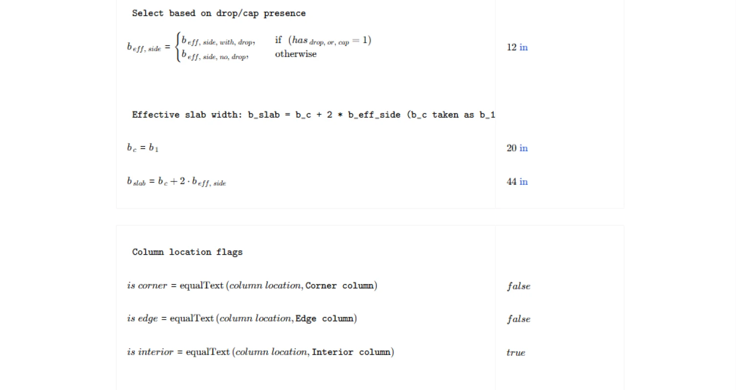
The baseline flexural fraction is computed directly from ACI 318-19 Equation 8.4.2.2.2 using the two column dimensions. The effective slab width is then established per Table 8.4.2.2.3, with separate expressions for slabs with and without drop panels or capitals, each capped against the distance to the slab edge to prevent the effective width from extending beyond the physical slab boundary.
The calculator then evaluates each applicable row of Table 8.4.2.2.4 independently. For each row, the column location and span direction determine which shear and strain limits apply, and the actual values of factored shear stress and net tensile strain are checked against those limits. If any applicable row passes both gate conditions and the slab is nonprestressed, the increase is permitted. The maximum modified gamma_f is set to 1.0 for corner columns and capped at the lesser of 1.25 times the baseline fraction or 1.0 for edge and interior column cases.
Outputs and Design Checks
The calculator reports four key results. The baseline fraction from Equation 8.4.2.2.2 gives the unmodified code value before any permitted increase is applied. The governing fraction used is the value that actually enters the moment calculation — either the baseline or the increased value, depending on whether the gate conditions were met. The effective slab width defines the strip over which the column moment is assumed to be uniformly distributed for reinforcement design. The moment resisted by the column by flexure is the product of the governing fraction and the total factored slab moment at the joint, giving the design moment demand that must be carried within the effective slab width per Clause 8.4.2.2.1.
Common Calculation Errors to Avoid
- Swapping b1 and b2 — b1 is always the column dimension in the direction of the moment being considered, and b2 is perpendicular to it. Reversing them changes the baseline gamma_f and every downstream result.
- Applying the Table 8.4.2.2.4 increase to prestressed slabs — the permitted increase applies only to nonprestressed two-way slabs. Using it for post-tensioned flat plates is a direct code violation.
- Ignoring the shear stress gate — the factored shear stress must be checked against the concrete shear capacity limit specific to the column location and span direction. Applying the increase based only on the strain check without satisfying the shear check is not permitted.
- Using the wrong strain threshold — the required net tensile strain relative to yield strain differs between corner columns and edge or interior columns. Applying the edge or interior threshold to a corner condition, or vice versa, produces an incorrect gate result.
- Neglecting the slab edge distance cap — the effective slab width cannot extend beyond the physical edge of the slab. Omitting the minimum check against the distance to the slab edge overstates the effective width, which reduces the required reinforcement density.
- Misidentifying the column location — corner, edge, and interior columns each have different rows in Table 8.4.2.2.4 with different limits. Classifying a column incorrectly changes which gate conditions apply and whether the increase is permitted at all.
Engineering templates
Common calculators
Design guides
FAQs
What does the fraction of slab moment resisted by column (γf) actually represent?
In a two-way slab system, the total factored moment at a slab-column joint is transferred partly by flexure and partly by eccentric shear. γf is the fraction assigned to flexure, per ACI 318-19 Cl. 8.4.2.2. The remainder (1 − γf) is transferred by eccentricity of shear. This split directly affects how much moment the column strip reinforcement within the effective slab width must be designed to carry.
What is the effective slab width b_slab and why does it matter?
The effective slab width defines the narrow band of slab over which the flexural moment transferred to the column is assumed to act. Per Table 8.4.2.2.3, it extends a limited distance either side of the column face, controlled by 1.5 times the slab thickness (or drop panel projection if present) and the distance to the slab edge. The reinforcement to resist Msc,col must be concentrated within this width, so undersizing it leads to unconservative bar spacing.
When is the increase to γf permitted under Table 8.4.2.2.4?
ACI 318-19 allows γf to be increased above its Eq. (8.4.2.2.2) baseline only when two gate conditions are simultaneously satisfied: the factored punching shear stress vu is below a limit that depends on column location (0.4vc for interior, 0.75vc for edge columns perpendicular to edge, etc.), and the net tensile strain εt in the extreme tension steel meets a minimum (εty + 0.003 for corner columns, εty + 0.008 for edge and interior). Both conditions must pass; failing either locks γf at the baseline value. The increase is also only applicable to nonprestressed slabs.
How do I set up a drop panel or column capital in this calculation?
Set the has_drop_or_cap flag to 1 and enter the projection of the drop panel or capital from the face of the column into drop_or_cap_proj. The calculation then switches the b_eff_side formula to the drop panel row of Table 8.4.2.2.3, using min(1.5 × drop projection, distance to slab edge + 1.5h). If no drop or capital is present, leave the flag at 0 and the projection input is ignored.
Why does column location and span direction affect the result?
Table 8.4.2.2.4 sets different vu limits depending on where the column sits in the floor plate and the direction of the moment being considered. Corner columns under either span direction and edge columns with moment parallel to the edge have the tightest shear limits. An interior column is more confined laterally, so punching demand is distributed differently. Selecting the wrong location or span direction can either miss a permitted increase or incorrectly apply one that ACI does not allow for that configuration.
What inputs feed into the final column moment Msc,col?
Msc,col = γf,used × Msc. The governing fraction γf,used is either the baseline γf from Eq. (8.4.2.2.2) or the increased value from Table 8.4.2.2.4 if all gate conditions pass. Msc is the total factored slab moment at the joint from your lateral or gravity analysis. Make sure Msc corresponds to the same direction as b1, since b1 is defined as the column dimension in the direction of the moment being transferred.
Learn about the benefits of using CalcTree on engineering projects!