Calculate Vs per ACI 318-19 Cl. 22.5.8.3 for RC sections. Get shear strength in x & y directions instantly. Try the free CalcTree template now.

This template is not available yet. You can sign up and create it yourself!
Or let us know if you'd like to be notified when it’s ready:
No items found.
No items found.
About this ACI 318-19: Shear Strength - Nominal Shear Strength Provided by Shear Reinforcement (Cl. 22.5.8.3) Calculator
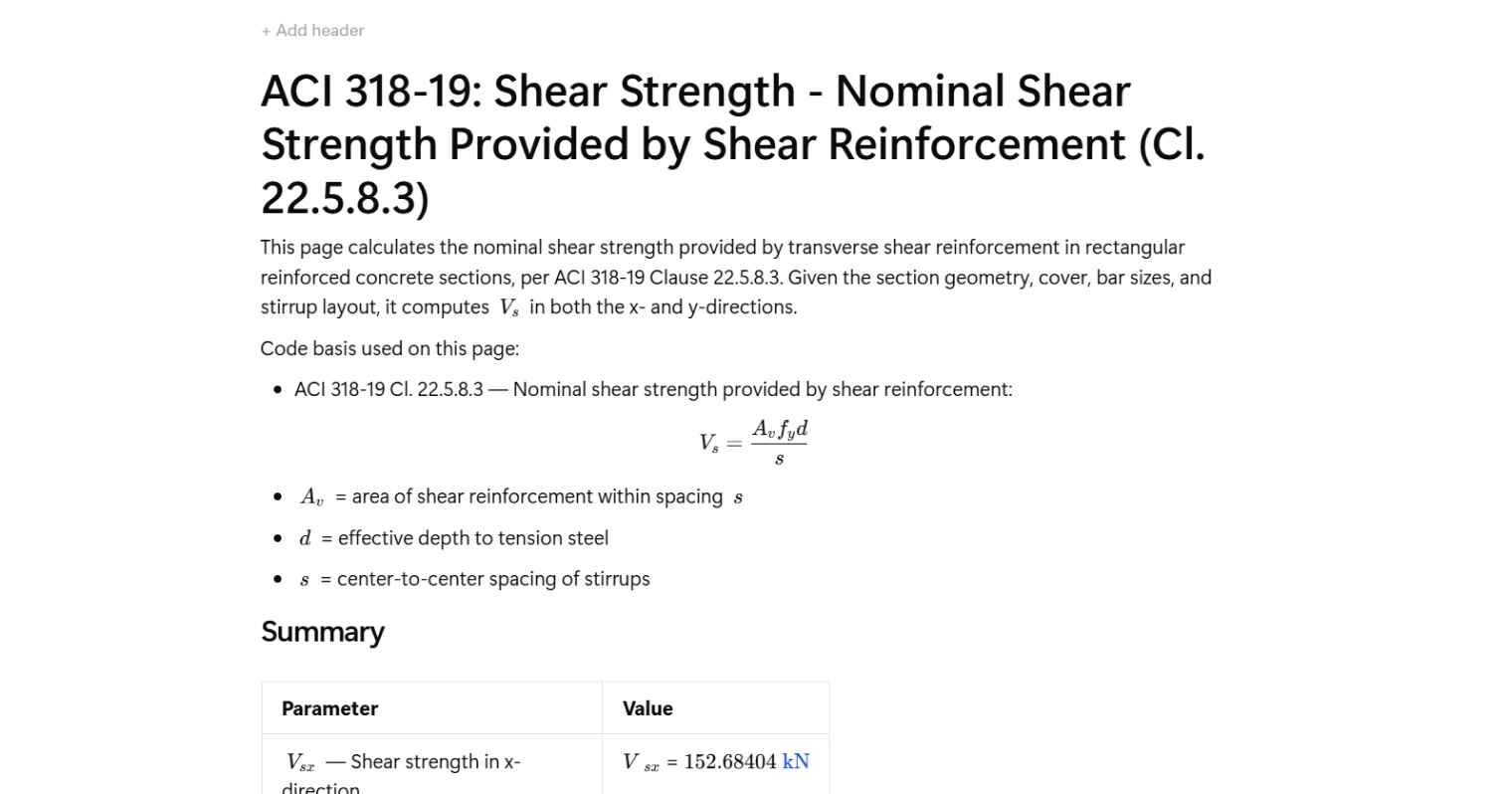
This calculator computes the nominal shear strength provided by transverse shear reinforcement in rectangular reinforced concrete sections, following ACI 318-19 Clause 22.5.8.3. Given the section geometry, clear cover, bar sizes, and stirrup layout, it calculates Vs independently in both the x- and y-directions, accounting for the correct effective depth and number of active stirrup legs in each direction.
- Structural engineer — verify shear reinforcement capacity in column or beam sections during detailing, with full transparency over effective depth, stirrup area, and spacing assumptions.
- RC detailer — check that a proposed stirrup layout and spacing satisfy shear demand before finalizing reinforcement drawings.
- Checking engineer — trace every intermediate value from gross geometry to final Vs to confirm compliance with ACI 318-19 during design review.
This is an engineering-grade calculator on CalcTree that exposes all intermediate steps — effective depths, stirrup leg areas, and directional shear strengths — so every value can be audited and adapted to your project.
More info on ACI 318-19: Shear Strength - Nominal Shear Strength Provided by Shear Reinforcement (Cl. 22.5.8.3)
Inputs
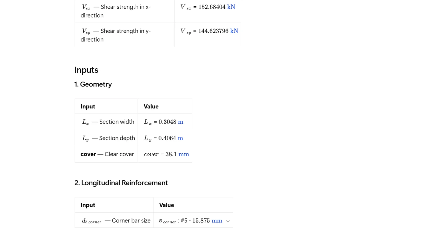
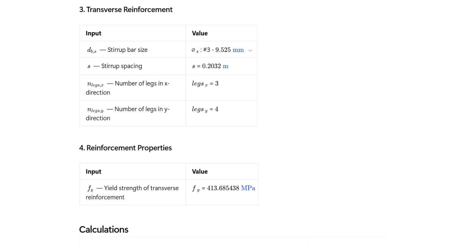
The calculator takes four categories of input. Section geometry defines the gross width and depth of the rectangular concrete section, along with clear cover to the outermost reinforcement. Longitudinal reinforcement is captured through the corner bar diameter, which directly affects the effective depth calculation. Transverse reinforcement inputs include the stirrup bar size, center-to-center stirrup spacing, and the number of stirrup legs acting in each direction. Finally, the yield strength of the transverse reinforcement is entered as a material property. These inputs fully define the geometry and reinforcement arrangement needed to evaluate shear capacity in both principal directions.
Effective Depth Calculation
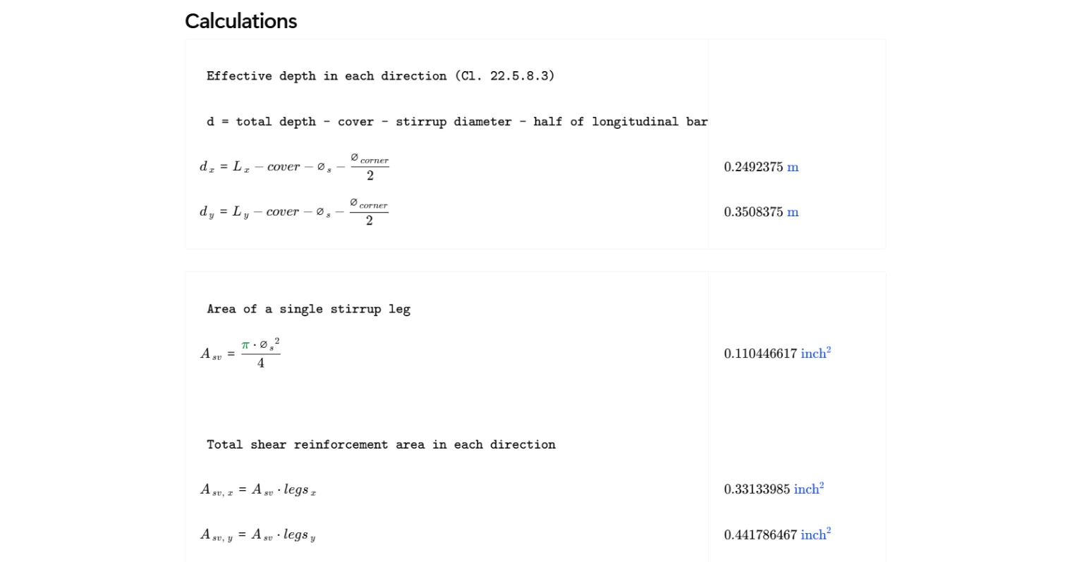
The effective depth in each direction is computed from the section dimensions by subtracting the clear cover, the stirrup bar diameter, and half the corner longitudinal bar diameter. Because the section has different gross dimensions in the x- and y-directions, the effective depths differ accordingly. Importantly, when calculating shear strength in a given direction, the effective depth used is the one measured perpendicular to that shear plane — so Vsx uses the effective depth in the y-direction, and Vsy uses the effective depth in the x-direction. This cross-directional relationship is a common source of error when performing the calculation by hand.
Shear Reinforcement Area
The area of a single stirrup leg is calculated from the stirrup bar diameter using the standard circular cross-section formula. The total shear reinforcement area for each direction, Av, is then obtained by multiplying the single-leg area by the number of legs active in that direction. The number of legs in the x- and y-directions can differ depending on the stirrup configuration, so both are entered independently. This ensures Av accurately reflects the reinforcement contributing to shear resistance in each direction rather than applying a single aggregate value.
Outputs and Design Checks
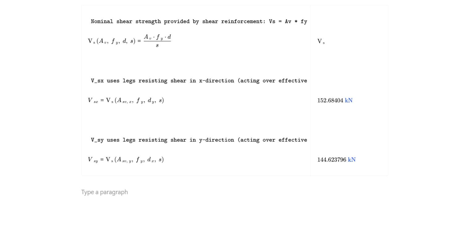
The calculator produces two output values: Vsx, the nominal shear strength provided by shear reinforcement resisting forces in the x-direction, and Vsy, the equivalent for the y-direction. Both are evaluated using the ACI 318-19 Cl. 22.5.8.3 expression Vs = Av · fy · d / s. These outputs represent the contribution of shear reinforcement alone and are intended to be combined with the concrete shear strength Vc to establish the total nominal shear capacity of the section. The results are reported in kips and can be directly compared against factored shear demands from analysis to confirm adequacy.
Common Calculation Errors to Avoid
- Swapping effective depth and shear direction — Vsx acts in the x-direction but is computed using the effective depth in the y-direction, and vice versa. Applying the same depth to both directions without this cross-mapping will give incorrect results.
- Using gross depth instead of effective depth — the effective depth must account for cover, stirrup diameter, and half the longitudinal bar diameter; using the full section dimension inflates Vs unconservatively.
- Applying total leg count instead of directional leg count — only the legs oriented to resist shear in a given direction should be included in Av for that direction; using the total number of legs regardless of orientation overstates capacity.
- Entering spacing as out-to-out instead of center-to-center — ACI 318-19 Cl. 22.5.8.3 requires center-to-center stirrup spacing; using a different spacing convention changes the result directly.
- Confusing fy for transverse and longitudinal steel — the yield strength entered here applies to the stirrups only; using the longitudinal bar yield strength, if different, is incorrect.
- Treating Vs as the total shear capacity — Vs from this clause is the reinforcement contribution only; it must be added to Vc to get the full nominal shear strength Vn before applying the strength reduction factor φ.
Engineering templates
Common calculators
Design guides
FAQs
What does ACI 318-19 Clause 22.5.8.3 actually calculate?
Cl. 22.5.8.3 gives the nominal shear strength contribution from transverse reinforcement (stirrups) in a reinforced concrete section. The formula Vs = Av × fy × d / s assumes the stirrups yield at the design shear plane and that the truss analogy holds. This Vs term is added to the concrete contribution Vc to get the total nominal shear capacity Vn.
Why are Vsx and Vsy calculated separately?
A rectangular section has different effective depths and potentially different stirrup leg counts in each principal direction. Shear in the x-direction is resisted by legs spanning in the x-direction, acting over the effective depth dy (measured in the y-direction), and vice versa. Treating them separately avoids over- or under-estimating capacity when the section is not square or when the stirrup layout is asymmetric.
How is the effective depth d calculated in this template?
The effective depth is measured from the extreme compression fiber to the centroid of the tension steel. Here it is computed as the overall section dimension minus clear cover, minus stirrup diameter, minus half the corner bar diameter. This applies in both the x and y directions using their respective overall dimensions.
What should I enter for number of stirrup legs in each direction?
Count the number of stirrup legs that cross the shear plane in each direction. For a standard perimeter hoop with no interior legs, that is 2 legs in each direction. Adding internal cross-ties increases this count. For example, a perimeter hoop plus one central cross-tie in the x-direction gives 3 legs in x and 2 legs in y.
Does this calculation include the strength reduction factor φ?
No. This template calculates the nominal shear strength Vs only. To get the design shear strength, multiply by φ = 0.75 per ACI 318-19 Cl. 21.2.1. You need to compare φVn = φ(Vc + Vs) against the factored shear demand Vu from your load combinations separately.
Are there upper limits on Vs that I need to check?
Yes. ACI 318-19 Cl. 22.5.1.2 limits the maximum Vs to 8√f'c × bw × d to prevent diagonal compression failures in the web. This template calculates Vs per Cl. 22.5.8.3 only and does not check that upper bound, so you should verify the limit independently once you have your concrete strength and section dimensions.
Learn about the benefits of using CalcTree on engineering projects!