Check ACI 318-19 Cl. 7.6.2.3 min. flexural reinforcement for prestressed one-way slabs with unbonded tendons. Instant pass/fail. Try it free on CalcTree.

This template is not available yet. You can sign up and create it yourself!
Or let us know if you'd like to be notified when it’s ready:
No items found.
No items found.
About this ACI 318-19: Minimum Flexural Reinforcement – Prestressed One-Way Slabs, Unbonded Tendons (Cl. 7.6.2) Calculator
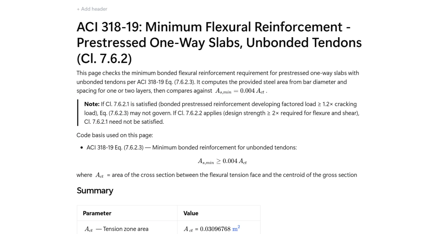
This calculator checks the minimum bonded flexural reinforcement requirement for prestressed one-way slabs with unbonded tendons per ACI 318-19 Clause 7.6.2. It computes the tension zone area, derives the minimum required steel area from Eq. (7.6.2.3), and compares it against the provided reinforcement from one or two bar layers — giving a clear pass/fail result.
- Structural engineer — verify minimum bonded reinforcement compliance for post-tensioned slab designs without manually working through the ACI clause hierarchy each time.
- PT slab designer — quickly iterate on bar size and spacing combinations to find an efficient layout that satisfies the minimum area threshold.
- Plan checker or reviewer — audit a submitted slab design against Eq. (7.6.2.3) with full traceability of inputs, intermediate values, and the governing check.
This is an engineering-grade calculator built on CalcTree, where every calculation step is visible, auditable, and shareable across your project team.
More info on ACI 318-19: Minimum Flexural Reinforcement – Prestressed One-Way Slabs, Unbonded Tendons (Cl. 7.6.2)
Inputs and Applicability
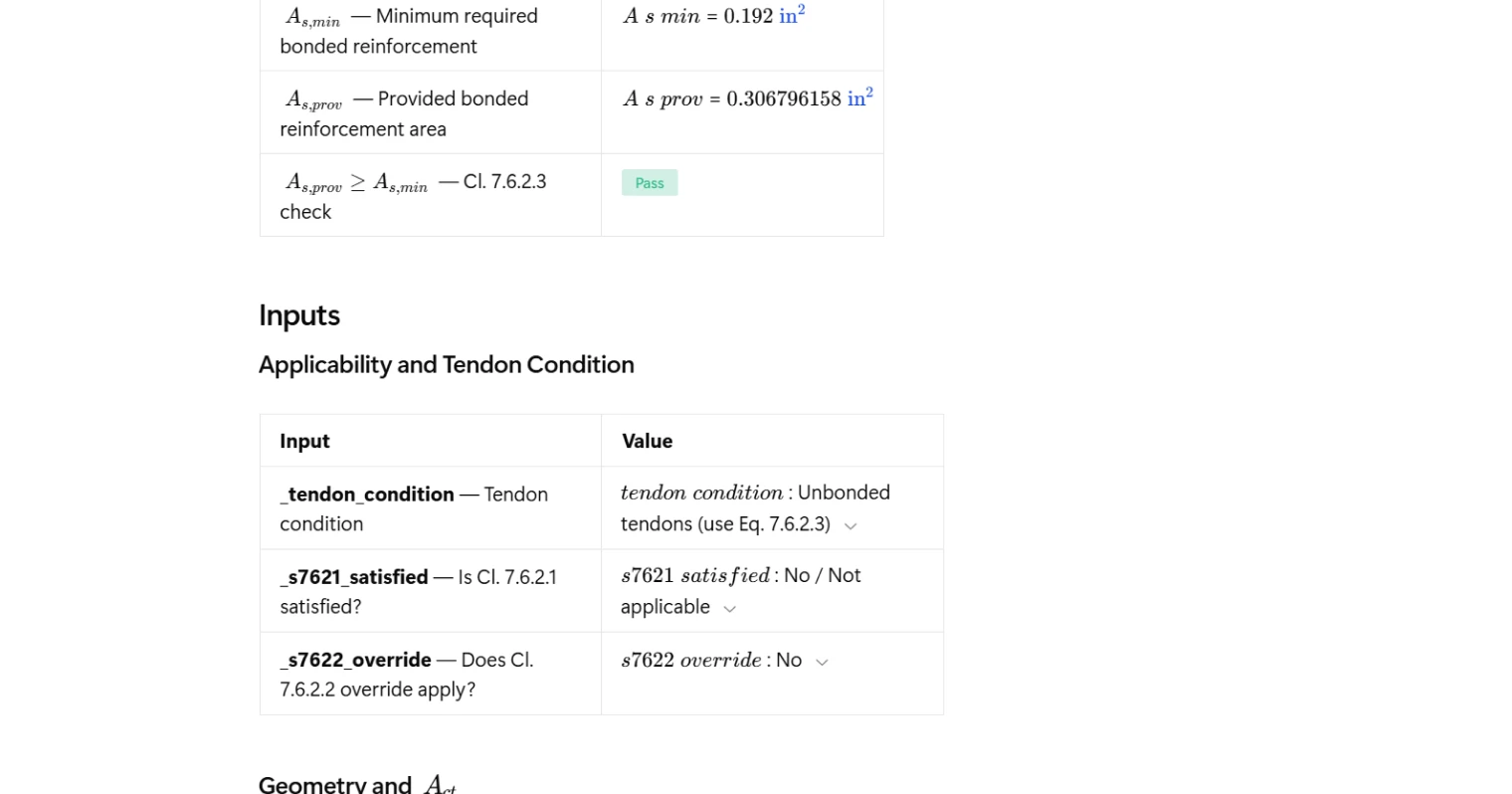
The calculator begins with three applicability selections that determine whether Eq. (7.6.2.3) governs. The user specifies whether the tendon condition involves unbonded tendons, whether Clause 7.6.2.1 is already satisfied by bonded prestressed reinforcement developing factored load capacity at least 1.2 times the cracking load, and whether the Clause 7.6.2.2 override applies where design strength meets or exceeds twice the required flexure and shear demand. These selections control the logic path before any geometry or reinforcement inputs are processed.
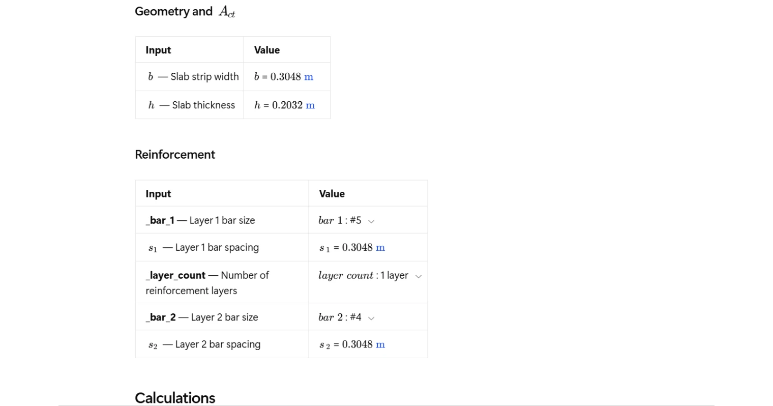
Geometry inputs are limited to slab strip width and slab thickness. For a rectangular section, the centroidal axis sits at mid-depth, so the tension zone area is computed directly from these two dimensions without requiring additional section properties.
Tension Zone Area and Minimum Reinforcement
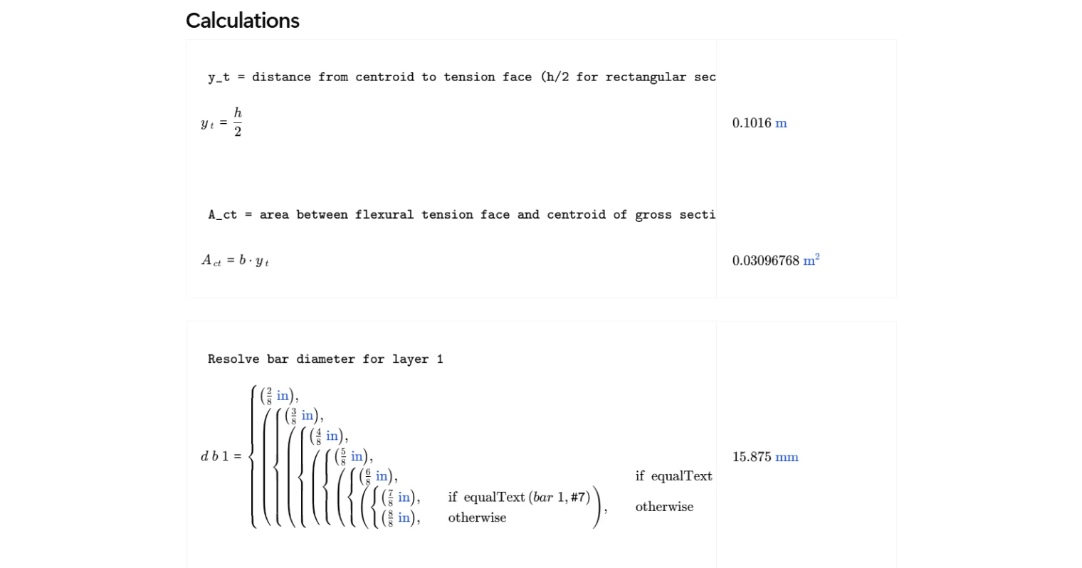
The tension zone area is defined by ACI 318-19 as the area of the cross section between the flexural tension face and the centroid of the gross section. For a uniform rectangular slab strip, the distance from the centroid to the tension face is half the slab thickness, making the tension zone area straightforward to calculate from strip width and total depth.
The minimum bonded reinforcement area required by Eq. (7.6.2.3) is then taken as a fixed proportion of that tension zone area. This limit exists because unbonded tendons do not develop bond along their length, so bonded mild steel reinforcement must be present to control crack widths and ensure adequate post-cracking ductility.
Provided Reinforcement Area
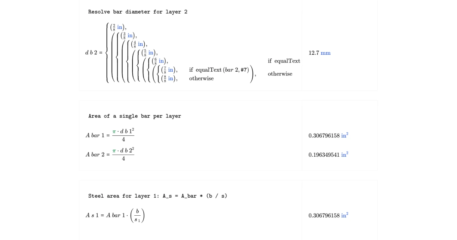
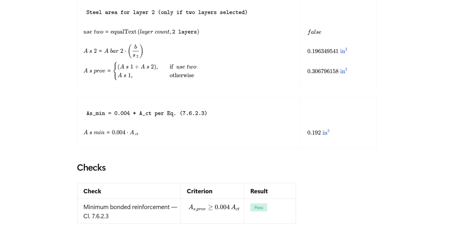
The calculator accepts one or two layers of bonded mild steel reinforcement. For each active layer, the user selects a standard bar size from a dropdown — ranging from No. 2 through No. 8 — and inputs the bar spacing. The bar diameter is resolved from the selected size, the individual bar area is computed from the cross-sectional area of a circle, and the steel area per unit strip width is determined from the ratio of bar area to spacing, then scaled to the full strip width. Where two layers are specified, the areas from both layers are summed to give the total provided reinforcement area.
Design Check
The final check compares the total provided bonded reinforcement area against the minimum required area from Eq. (7.6.2.3). The result is displayed as a clear pass or fail. A summary table at the top of the page collects the tension zone area, minimum required area, provided area, and check result in one place for quick review. All intermediate values remain visible throughout the calculation for full auditability.
Common Calculation Errors to Avoid
- Skipping the applicability check — applying Eq. (7.6.2.3) without first confirming whether Cl. 7.6.2.1 or Cl. 7.6.2.2 applies can lead to unnecessary or incorrect reinforcement requirements; work through the clause hierarchy in order.
- Using the full section area instead of the tension zone — the code requires the area between the flexural tension face and the centroidal axis only, not the full gross section area; using the full depth doubles the required reinforcement.
- Assuming mid-depth centroid for non-rectangular sections — for T-sections or slabs with significant voids, the centroid does not sit at half the total depth and must be calculated explicitly before determining the tension zone area.
- Mixing bonded and unbonded steel in the provided area — only bonded mild steel reinforcement counts toward satisfying Eq. (7.6.2.3); unbonded tendons cannot be included in the provided area for this check.
- Applying the strip width inconsistently — the slab strip width used to compute the tension zone area and the strip width used to calculate provided reinforcement from bar spacing must be the same; mixing design strip and tributary widths introduces error.
- Omitting a second reinforcement layer — where two layers are present, failing to include both in the provided area will understate the total steel and may produce a false fail result.
Engineering templates
Common calculators
Design guides
FAQs
Why do unbonded tendons require minimum bonded reinforcement?
Unbonded tendons do not develop significant bond with the surrounding concrete, so at cracking, the slab cannot redistribute tension forces along its length the way a bonded system can. Without supplemental bonded bars, a single crack can open wide and become uncontrolled. ACI 318-19 Cl. 7.6.2.3 addresses this by requiring a minimum area of bonded mild steel to provide crack control and ensure adequate post-cracking behavior.
What is A_ct and how is it calculated here?
A_ct is the area of the gross cross section between the flexural tension face and the centroid. For a rectangular slab section, the centroid sits at h/2, so A_ct simply equals b × (h/2), where b is the slab strip width and h is the total slab thickness. This calculation uses the gross section, not the transformed or cracked section.
When does the Cl. 7.6.2.3 minimum not govern?
Two situations can override or waive the Eq. (7.6.2.3) requirement. First, if bonded prestressed reinforcement alone develops a factored flexural strength of at least 1.2 times the cracking moment (Cl. 7.6.2.1), then Eq. (7.6.2.3) need not govern. Second, if the design strength exceeds twice the required strength for both flexure and shear (Cl. 7.6.2.2), Cl. 7.6.2.1 need not be satisfied at all. Use the applicability dropdowns in the Inputs section to flag which condition applies before reading the check result.
How does the tool compute the provided steel area from bar size and spacing?
For each layer, the calculation resolves the selected bar designation to a diameter, computes the single-bar area as π·d²/4, then multiplies by the ratio of strip width to bar spacing: A_s = A_bar × (b / s). If two layers are selected, both layer areas are summed to give A_s,prov. This is the value compared against 0.004·A_ct.
What strip width b should I use as input?
Use the tributary width you are designing for, typically a 12-inch unit strip for uniform slab checks or the full panel width if you are designing a band of reinforcement. Keep b consistent between the geometry and reinforcement inputs, since A_ct, A_s,min, and A_s,prov all scale linearly with b, so the pass/fail result is independent of strip width for uniform bar layouts.
The check is failing — what are my options?
Either reduce bar spacing, increase bar size, or add a second layer of reinforcement. Because A_s,min = 0.004 × b × h/2, increasing slab thickness also raises the required area, so thickening the slab alone will not fix a failing check. Focus on increasing provided steel. Adding a second layer is often the most practical fix for thicker slabs where single-layer spacing is already at a practical minimum.
Learn about the benefits of using CalcTree on engineering projects!