ACI 318-19 moment magnification for nonsway frames (Cl. 6.6.4.5): instantly compute Cm, δ, and Mc. Try the free CalcTree template now.

This template is not available yet. You can sign up and create it yourself!
Or let us know if you'd like to be notified when it’s ready:


No items found.
No items found.
About this ACI 318-19: Moment Magnification - Nonsway Frames (Cl. 6.6.4.5) Calculator
This calculator implements the moment magnification method for nonsway frames per ACI 318-19 Cl. 6.6.4.5. It steps through the full procedure: computing the minimum end moment, evaluating the correction factor based on loading condition, calculating the magnification factor, and returning the design factored moment to use in member design.
- Structural engineer — apply the moment magnification method to slender columns in nonsway frames directly from factored loads and critical buckling load, with every intermediate value exposed for checking.
- RC design checker — verify that slenderness effects have been properly accounted for in column design by tracing the magnification factor back through its inputs.
- Graduate engineer — follow the ACI 318-19 clause-by-clause logic with clearly labelled equations to build familiarity with code-compliant slender column design.
This is an engineering-grade calculator built on CalcTree, where every equation references its ACI 318-19 source clause and all intermediate results are visible and auditable within your project workspace.
More info on ACI 318-19: Moment Magnification - Nonsway Frames (Cl. 6.6.4.5)
Inputs
The calculator takes five primary inputs. The factored axial load and the two end moments — the lesser and greater by absolute value — are the core loading parameters. The sign of the moment ratio follows the ACI 318-19 convention: negative for single curvature and positive for double curvature, which directly affects the correction factor. The member depth is used solely in the minimum eccentricity check. The critical buckling load, which accounts for member stiffness and effective length, is supplied by the user and enters the magnification factor denominator. A dropdown selection determines whether transverse loads act between supports, which governs which form of the correction factor applies.
Method and Equations
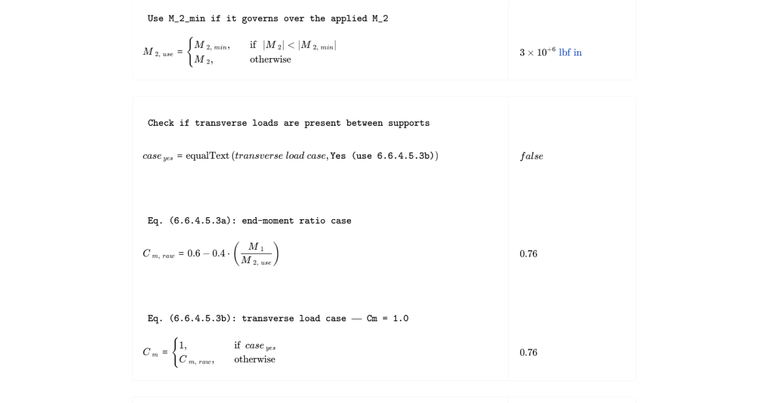
The calculation follows a linear sequence of four ACI 318-19 equations. First, the minimum end moment is computed from the factored axial load and member depth, establishing a lower bound on the moment used in design. The governing end moment is then taken as whichever is larger in absolute value between the applied moment and the minimum. Next, the correction factor accounts for the shape of the moment diagram along the member length: when no transverse loads act between supports, it is computed from the end moment ratio; when transverse loads are present, it defaults to unity per Cl. 6.6.4.5.3b. The magnification factor is then computed as the ratio of the correction factor to a stability reduction term based on the ratio of factored axial load to critical buckling load, with a minimum enforced value of 1.0. Finally, the design factored moment is the product of the magnification factor and the governing end moment.
Outputs and Design Checks
The summary table presents the five key outputs: the minimum end moment, the governing end moment used in subsequent calculations, the correction factor, the magnification factor, and the design factored moment. The magnification factor has a code-prescribed lower bound of 1.0, which this calculator enforces explicitly. The design factored moment is the value that should be used in cross-section design for combined axial load and bending. No separate capacity check is performed here — the output feeds into the interaction diagram assessment for the column section.
Common Calculation Errors to Avoid
- Incorrect sign on the moment ratio — assigning the wrong sign to M₁/M₂ is one of the most common mistakes. Single curvature gives a negative ratio and increases the correction factor, while double curvature gives a positive ratio and reduces it. Reversing the sign unconservatively underestimates the magnified moment.
- Using M₁ and M₂ in the wrong order — M₂ must always be the end moment with the greater absolute value. Swapping them produces an incorrect moment ratio and an unreliable correction factor.
- Neglecting the minimum end moment check — skipping the M₂,min calculation can result in using an end moment that is too small, particularly for lightly loaded columns with small applied eccentricities.
- Supplying an incorrect critical buckling load — the magnification factor is highly sensitive to Pₓ. Errors in effective length, stiffness assumptions, or boundary conditions feed directly into the denominator and can produce unconservative results.
- Ignoring the minimum magnification factor of 1.0 — if the raw calculated value of δ falls below 1.0, the code requires it be taken as 1.0. Applying a sub-unity magnifier is not permitted and reduces the design moment below the unfactored input.
- Applying this method to sway frames — the moment magnification method in Cl. 6.6.4.5 applies only to nonsway frames. Using it for sway-classified frames requires the procedure in Cl. 6.6.4.6, which accounts for lateral drift amplification differently.
Engineering templates
Common calculators
Design guides
FAQs
What is the moment magnification method and when does it apply?
The moment magnification method is an approximate second-order analysis that accounts for P-delta effects in slender columns by amplifying the first-order design moment. For nonsway frames per ACI 318-19 Cl. 6.6.4.5, it applies to columns restrained against lateral drift, where the primary concern is member curvature under axial load, not story-level sidesway. Use it when your frame qualifies as nonsway and the column slenderness ratio klu/r exceeds the limits in Cl. 6.2.5 that permit slenderness to be neglected.
What is the sign convention for M1 and M2, and why does it matter?
ACI 318-19 defines M1/M2 as negative for single curvature (both moments cause the same bowing direction) and positive for double curvature (moments bend the column in an S-shape). Getting this sign wrong directly affects Cm via Eq. (6.6.4.5.3a). Single curvature gives a larger Cm and therefore a larger magnification factor, which is the conservative case. Double curvature reduces Cm, reflecting that the column is less prone to buckling when moments partially counteract each other along the length.
When does the calculator override M2 with M2,min?
ACI 318-19 Eq. (6.6.4.5.4) sets a minimum end moment of Pu(0.6 + 0.03h) to account for accidental eccentricity in columns with very small applied moments. If the applied M2 is smaller in absolute value than M2,min, the calculation uses M2,min as the governing moment for both the Cm and Mc calculations. This is common in lightly loaded interior columns or columns designed primarily for axial load.
When should I set the transverse load case to "Yes"?
Select "Yes (use 6.6.4.5.3b)" when the column has distributed loads, point loads, or any transverse loading applied between its two ends, such as a column supporting a beam reaction mid-height or a wall with lateral earth pressure. In that case, the end-moment ratio M1/M2 no longer captures the critical curvature shape, so ACI conservatively sets Cm = 1.0 per Eq. (6.6.4.5.3b). If loads are only applied at the member ends, use the default Eq. (6.6.4.5.3a) option.
What happens if the magnification factor delta comes out less than 1.0?
The calculation enforces a minimum of δ = 1.0 per ACI 318-19 Eq. (6.6.4.5.2). A raw value below 1.0 can occur when Pu is small relative to Pc and Cm is low due to strong double curvature. In that case the amplification is negligible and the design moment Mc simply equals δ·M2,use with δ = 1.0.
What should I do if the denominator in the magnification factor approaches zero or goes negative?
If Pu approaches or exceeds 0.75Pc, the denominator in Eq. (6.6.4.5.2) collapses, producing an extremely large or undefined δ. This signals that the column is near or beyond its elastic critical load and the moment magnification method is no longer valid. You need to either increase the column section or reinforcement to raise Pc, reduce the applied axial load, or perform a full nonlinear second-order analysis. The 0.75 factor is a stiffness reduction factor that already accounts for cracking and variability, so a result near this limit is a serious design flag, not just a numerical issue.
Learn about the benefits of using CalcTree on engineering projects!