Calculate ACI 318-19 cracking torsion Tcr for solid and hollow sections per 22.7.5.1. Covers all 3 member cases. Try it free on CalcTree.

This template is not available yet. You can sign up and create it yourself!
Or let us know if you'd like to be notified when it’s ready:
No items found.
No items found.
About this ACI 318 Cracking Torsion (Tcr) Calculator
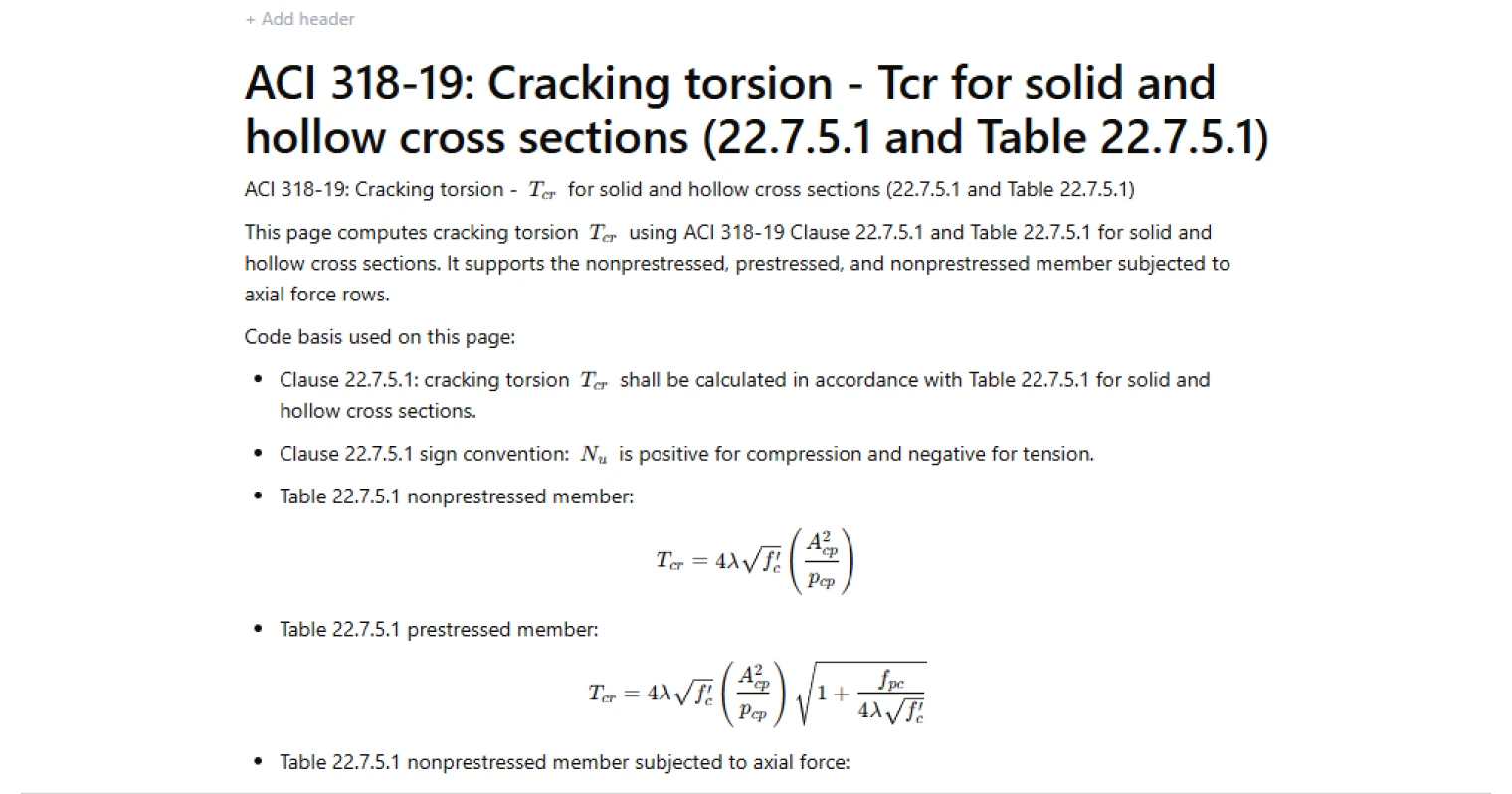
This calculator computes the cracking torsion (T_{cr}) for reinforced concrete members using the provisions of ACI 318-19 Clause 22.7.5.1 and Table 22.7.5.1. The calculation evaluates the torsional moment at which cracking is expected to initiate in a concrete member, based on the concrete strength, cross-section geometry, and member condition (nonprestressed, prestressed, or nonprestressed with axial force).
- Structural engineer — check torsional cracking capacity when designing beams or edge members subjected to torsion.
- Bridge or infrastructure engineer — evaluate torsional cracking limits in girders or box sections where torsion governs service behavior.
- Engineering consultant or reviewer — verify torsional cracking calculations and confirm compliance with ACI 318 provisions.
The calculator implements the equations directly from ACI 318-19 Table 22.7.5.1 and exposes intermediate terms such as the geometric torsion parameter and row modifiers for transparency. It is an engineering-grade calculator that can be reviewed, reused, and shared within CalcTree.
More info on Cracking Torsion (Tcr)
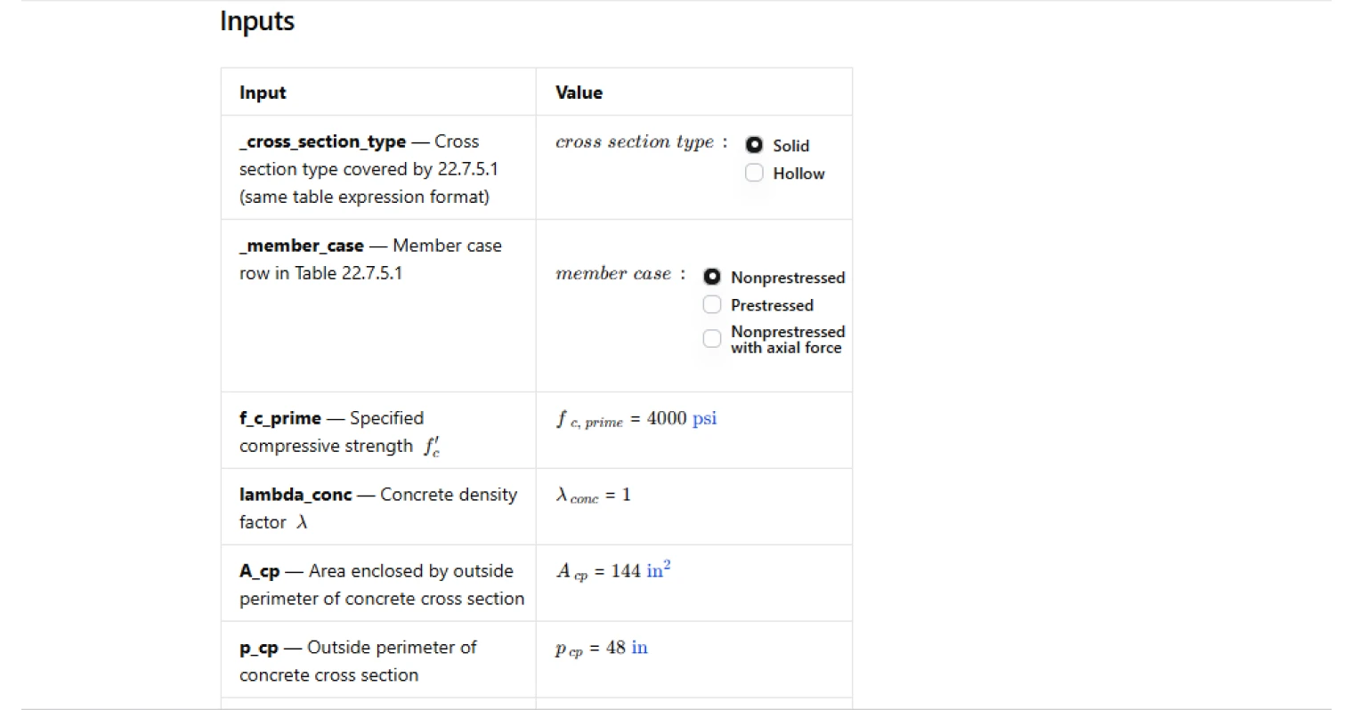
Inputs
The calculation requires the concrete compressive strength, the lightweight concrete modification factor, and geometric parameters describing the cross-section. The key geometry term uses the area enclosed by the outside perimeter of the cross section and the perimeter length itself.
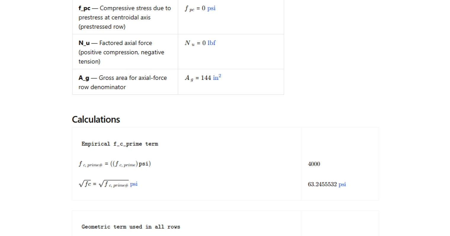
Users must also specify the applicable member condition from ACI 318 Table 22.7.5.1: nonprestressed, prestressed, or nonprestressed with axial force. When the prestressed row is selected, the compressive stress due to prestress is included in the equation. When the axial-force row is selected, the factored axial force and gross area of the section are required.
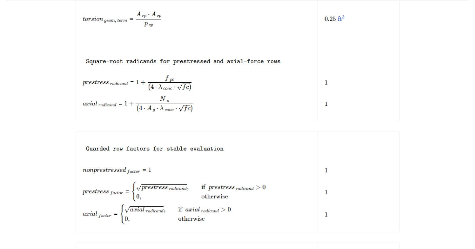
Geometric torsion parameter
A central component of the calculation is the geometric term involving the square of the area enclosed by the concrete perimeter divided by the perimeter itself. This parameter captures the influence of cross-section shape and size on torsional resistance.
Larger enclosed areas relative to perimeter length increase the cracking torsion capacity because the section can resist torsional stresses more effectively before cracking occurs.
Row modifiers for member type
The equations in Table 22.7.5.1 apply modification factors depending on the member type:
- Nonprestressed members use the base equation.
- Prestressed members include an additional square-root factor that accounts for the beneficial effect of compressive prestress.
- Nonprestressed members subjected to axial force include a similar square-root factor that reflects the influence of axial compression or tension on torsional cracking capacity.
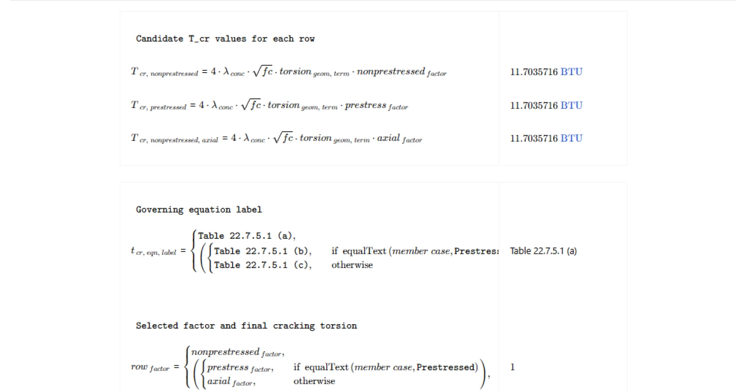
The calculator evaluates the relevant radicand for the selected row and applies the appropriate factor to the base torsion equation.
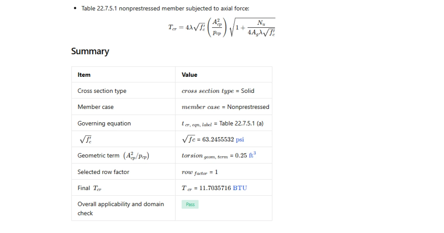
Outputs and checks
The primary output is the cracking torsion (T_{cr}), which represents the torsional moment at which diagonal cracking is expected to initiate in the concrete.
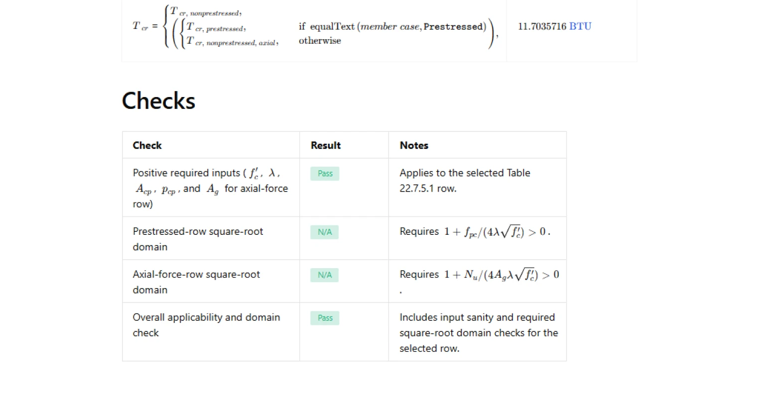
Supporting outputs include the square root of the concrete strength term, the geometric torsion parameter, and the modifier associated with the selected member case. The calculator also performs checks to confirm that required inputs are positive and that square-root expressions remain within a valid mathematical domain.
Common Calculation Errors to Avoid
- Using incorrect section geometry — the area and perimeter must correspond to the outer concrete boundary of the section, not the core inside reinforcement.
- Ignoring axial force sign conventions — axial compression and tension affect the cracking torsion differently, so the sign of the axial force must follow the ACI convention.
- Applying prestressed equations to nonprestressed members — the prestressed row includes additional stress terms that should only be used when prestressing is present.
- Providing inconsistent units — concrete strength, axial force, and section geometry must all be entered in compatible units to avoid scaling errors.
- Neglecting domain limits in square-root terms — the prestress and axial-force factors require positive radicands; invalid values can lead to nonphysical results.
Engineering templates
Common calculators
Design guides
FAQs
What is cracking torsion and why does it matter?
Cracking torsion Tcr is the torsional moment at which a concrete cross section first develops diagonal cracking. ACI 318-19 uses it as a threshold: if the factored torsion Tu is below a fraction of Tcr (specifically φ·Tcr/4), torsion can be ignored in design. Above that threshold, torsion must be explicitly designed for. Getting Tcr right determines whether torsion governs your reinforcement detailing at all.
What is the geometric term Acp²/pcp and how do I calculate it?
Acp is the total area enclosed by the outside perimeter of the concrete cross section, including any hollow interior. pcp is the length of that outside perimeter. The ratio Acp²/pcp has units of length cubed and captures the efficiency of the cross section in resisting torsion. For a solid rectangular section b×h, Acp = b·h and pcp = 2(b+h). For a hollow section, ACI 318-19 still uses the outside perimeter dimensions for both terms in Table 22.7.5.1.
What is the lambda factor and what value should I use?
Lambda λ is the concrete density modification factor from ACI 318-19 Section 19.2.4. For normalweight concrete, λ = 1.0. For lightweight concrete, λ is reduced based on the equilibrium density or the fraction of natural sand used. If you are using lightweight concrete, check Table 19.2.4.2 for the correct value before entering it into this calculation.
How does axial force affect cracking torsion, and what sign convention applies?
A compressive axial force increases Tcr because it suppresses diagonal tension cracking. A tensile axial force reduces it. ACI 318-19 Clause 22.7.5.1 is explicit: Nu is positive for compression and negative for tension. Enter Nu with the correct sign or the radicand in the axial-force row equation will be unconservative. The calculation includes a domain check that flags a Fail if the radicand goes negative, which would indicate the section is severely tension-dominated.
When does the axial-force row fail its domain check?
The axial-force equation contains the term 1 + Nu/(4·Ag·λ·√f'c) under a square root. If the tensile axial force is large enough to make this expression zero or negative, the square root is not real and the ACI equation is not applicable. In that condition the calc flags Fail. This situation indicates the section is under very high net tension and Tcr effectively drops to zero or the member should be re-evaluated for combined tension and torsion using a different approach.
Can this calculation be used directly to check whether torsion can be neglected?
This page calculates Tcr only. To check whether torsion can be neglected, compare your factored torsion Tu against the threshold φ·Tcr/4 per ACI 318-19 Clause 22.7.1.1, where φ = 0.75 for torsion. If Tu ≤ φ·Tcr/4, torsion effects can be ignored. That comparison is a separate step not performed here, but Tcr from this page feeds directly into it.
Learn about the benefits of using CalcTree on engineering projects!