Check ACI 318-19 brackets and corbels dimensional limits (16.5.1.1, 16.5.2) instantly. Verify applicability, depth, and shear limits. Try it free on CalcTree.

This template is not available yet. You can sign up and create it yourself!
Or let us know if you'd like to be notified when it’s ready:


No items found.
No items found.
About this ACI 318 Brackets and Corbels Applicability and Dimensional Limits Calculator
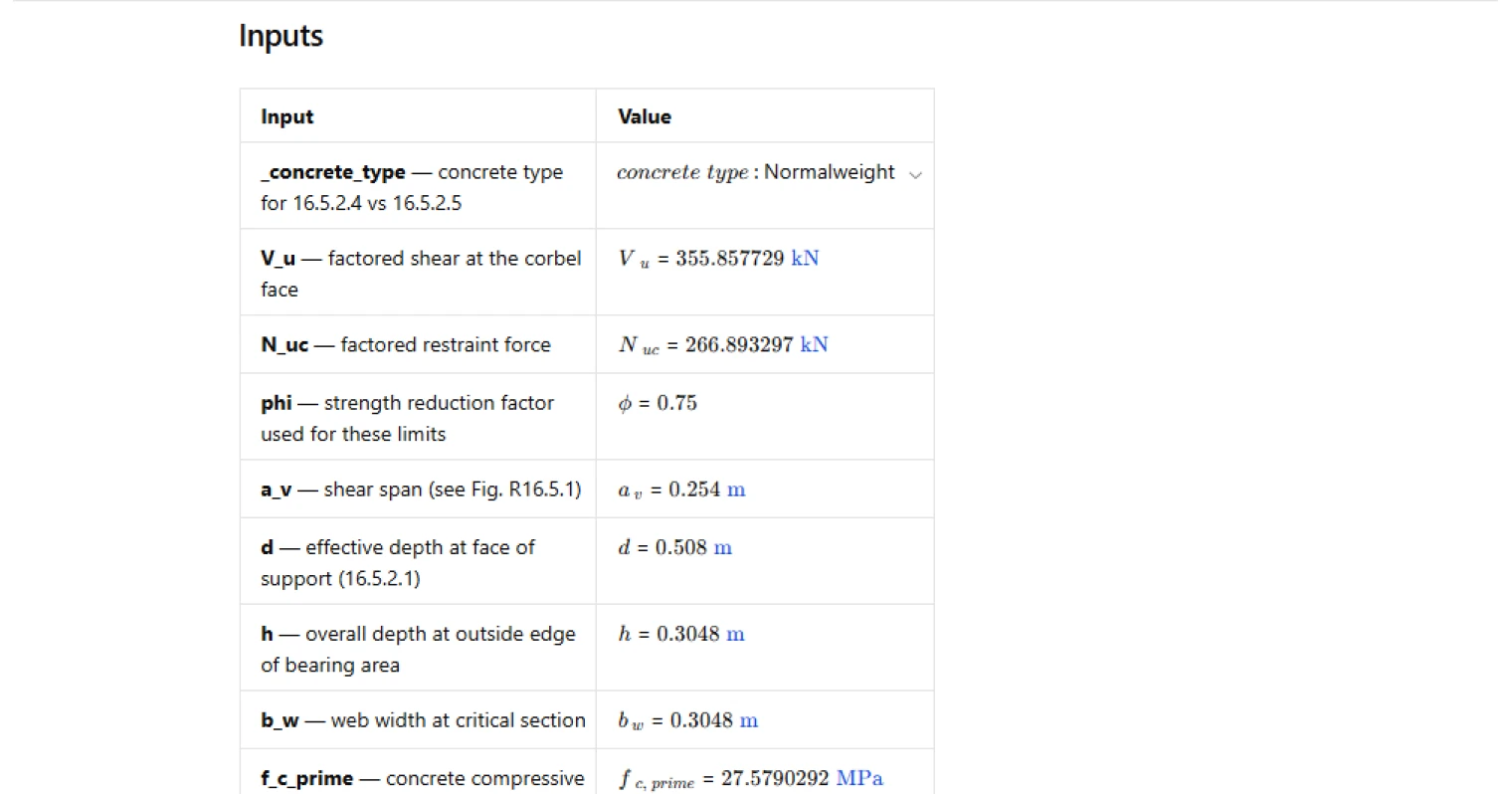
This calculator checks whether a concrete bracket/corbel can be designed using the ACI 318-19 bracket-and-corbel provisions, and whether basic geometric and shear-stress-style dimensional limits are satisfied per ACI 318-19 16.5.1.1 and 16.5.2. It focuses on applicability (shear-span ratio and restraint force condition), bearing projection limits, and the governing limit on (V_u/\phi) based on concrete type.
- Structural engineer — quickly confirm a corbel/bracket concept is within the ACI 16.5 scope ((a_v/d), (N_{uc}) vs (V_u)) before investing time in reinforcement detailing.
- Detailer / BIM technician — validate that the bearing projection and depth-at-bearing-edge constraints won’t be violated by connection geometry and bar anchorage assumptions.
- Checker / reviewer — audit the governing limit (V_{lim}) selection (normalweight vs lightweight) and confirm the controlling inequality driving a pass/fail outcome.
It’s an engineering-grade calculator on CalcTree: inputs are explicit, intermediate limit terms are surfaced (including the governing (V_{lim})), and the final check is traceable back to the cited ACI clauses.
More info on ACI 318 Brackets and Corbels Applicability and Dimensional Limits
Applicability checks
The page first verifies that the bracket/corbel falls within the ACI 16.5 design approach by checking the shear-span ratio (a_v/d) against the ACI limit and confirming the restraint force condition (N_{uc} \le V_u). These checks act as gate conditions: if either is not satisfied, the member is outside the intended applicability for the 16.5 provisions used here.
Bearing projection limit logic
The bearing projection check compares the user-defined bearing projection (a_{proj}) to an allowable limit distance measured from the face of support. The limit is taken as the end of the straight portion of the primary tension reinforcement, unless a transverse anchor bar is provided, in which case the more restrictive of the straight-bar limit and the anchor-bar interior-face limit governs. This mirrors the intent of controlling where the bearing can occur relative to the tension tie anchorage.
Dimensional shear-stress-style limit (V_{lim})
For dimensional limits, the page computes a governing allowable limit (V_{lim}) and checks (V_u/\phi \le V_{lim}). For normalweight concrete, (V_{lim}) is taken as the least of three expressions proportional to (b_w d) with strength-dependent caps. For lightweight concrete, (V_{lim}) is taken as the lesser of two expressions that reduce with increasing (a_v/d), reflecting the penalty applied in the lightweight clause form. The concrete type input switches between these two clause sets and the calculator reports the governing (V_{lim}) used for the check.
Outputs and pass/fail summary
The key reported outputs are the computed shear-span ratio (a_v/d), the demand term (V_u/\phi), the governing limit (V_{lim}), and an overall traffic-light result. The overall result fails if any individual check fails: applicability, depth at bearing edge, bearing projection, or the (V_u/\phi) dimensional limit. This makes it straightforward to identify which clause condition is controlling the outcome for iteration.
Common Calculation Errors to Avoid
- Using the wrong (d) location — (d) is taken at the face of support for these provisions; using a depth taken elsewhere can distort (a_v/d) and the dimensional limit terms.
- Treating (\phi) as implicit — this page treats (\phi) as an input; using an inconsistent (\phi) (or forgetting to divide by it when comparing to limits) can flip the governing check.
- Incorrect normalweight vs lightweight selection — selecting the wrong concrete type applies the wrong clause set and can materially change (V_{lim}), especially when the lightweight expressions include (a_v/d) dependence.
- Not enforcing bearing projection geometry — checking shear capacity without confirming (a_{proj}) is within the reinforcement anchorage-based limit can lead to a detail that is noncompliant even if strength checks pass.
- Forgetting the restraint force applicability condition — overlooking (N_{uc} \le V_u) can place the member outside the intended scope of the simplified 16.5 approach used here.
- Mixing units in strength-based expressions — ensure (f'c), (b_w), (d), and shear terms are in a consistent unit system before computing (V{lim}) and comparing to (V_u/\phi).
Engineering templates
Common calculators
Design guides
FAQs
What is the purpose of checking dimensional limits before designing a corbel?
ACI 318-19 Section 16.5 uses a strut-and-tie or shear-friction model that only applies within defined geometric and loading bounds. If the shear span ratio, depth, or shear demand falls outside those bounds, the design equations are not valid. These checks confirm you can proceed with the Section 16.5 design procedure before doing any reinforcement calculations.
What does the shear span ratio av/d represent and why is it capped at 1.0?
The shear span av is the horizontal distance from the load to the face of the support; d is the effective depth at that face. Their ratio characterizes how much bending versus direct shear is driving behavior. ACI 318-19 Section 16.5.1.1 limits av/d to 1.0 because the corbel design method assumes predominantly shear-dominated load transfer. Beyond that ratio, beam theory governs and the corbel provisions no longer apply.
Why does ACI 318-19 require h at the outer bearing edge to be at least 0.5d?
Section 16.5.2.2 sets this minimum to prevent a brittle diagonal tension failure at the re-entrant corner at the outer edge of the bearing. If the depth tapers too aggressively, that corner becomes a weak point that the reinforcement detailing cannot adequately address.
How does the calculation determine the bearing projection limit from Section 16.5.2.3?
The bearing area must not extend beyond the end of the straight portion of the primary tension reinforcement. If you have also provided a transverse anchor bar, the interior face of that bar is an additional limit. The calculation takes the more restrictive of whichever limits apply and checks that your input bearing projection a_proj stays within that distance.
What inputs change if I switch from normalweight to lightweight concrete?
Switching to lightweight concrete activates the Section 16.5.2.5 limits instead of 16.5.2.4. The lightweight expressions for the shear capacity limit V_lim both include the shear span ratio av/d explicitly, so the governing limit also depends on your geometry, not just concrete strength and section size. The normalweight limits are av/d-independent. Make sure to select the correct concrete type in the dropdown before reviewing results.
What should I do if the overall check fails on the dimensional limit for Vu/phi?
A fail on the Vu/phi vs V_lim check means the section is too small for the applied shear, regardless of reinforcement. The fix is to increase bw, d, or both to bring Vu/phi below the governing limit. Increasing f'c can help but is often less efficient since two of the three normalweight limits are either capped or weakly dependent on concrete strength. Resize the section first, then rerun the check before proceeding to reinforcement design.
Learn about the benefits of using CalcTree on engineering projects!