ACI 318-19 bearing strength calculator (Section 22.8). Instantly compute φBn and Bn for concrete members. Try the free CalcTree template now.

This template is not available yet. You can sign up and create it yourself!
Or let us know if you'd like to be notified when it’s ready:


No items found.
No items found.
About this ACI 318-19: Bearing Strength - Design and Nominal Bearing Strength (Section 22.8) Calculator
This calculator computes the nominal bearing strength and design bearing strength of concrete members in bearing per ACI 318-19 Section 22.8. It covers all three cases defined in Table 22.8.3.2, applying the appropriate formula based on the relationship between the loaded area and the supporting surface area, then checking the result against the factored bearing force.
- Structural engineer — verify bearing strength at column bases, corbels, and bearing plates in one step, with case selection and the area ratio factor applied automatically.
- Project engineer — run code-compliant bearing checks during design development or peer review without manually working through the ACI table conditions.
- Construction engineer — confirm that temporary bearing conditions on concrete elements during erection meet ACI 318-19 strength requirements before work proceeds.
This is an engineering-grade calculator built on CalcTree, where inputs, equations, and checks are fully traceable and the calculation can be saved directly to a project workspace.
More info on ACI 318-19: Bearing Strength - Design and Nominal Bearing Strength (Section 22.8)
Inputs
The calculator requires four primary inputs: concrete compressive strength, the loaded area, the supporting surface area, and the factored bearing force. The loaded area is the contact area through which the compressive force is transferred, and the supporting surface area is determined by projecting a frustum from the loaded area at a 1-vertical-to-4-horizontal slope to the base of the support. The user also selects the applicable case from Table 22.8.3.2 and a strength reduction factor consistent with the bearing condition being checked.
Nominal Bearing Strength
The nominal bearing strength is calculated according to which of the three cases in Table 22.8.3.2 applies. Where the supporting surface is wider than the loaded area, the code permits an increase in the permissible bearing stress through the area ratio term, subject to an upper limit. Where the two areas are equal, a fixed multiplier applies directly to the loaded area. For all other conditions, the basic permissible bearing stress of 0.85f'c is used without modification. The area ratio term accounts for the confinement benefit provided when a larger mass of concrete surrounds the loaded region, and the pyramid or frustum rule governs the geometry used to establish that ratio.
Design Bearing Strength and Code Check
The design bearing strength is obtained by applying the ACI 318-19 strength reduction factor to the nominal bearing strength. The calculator then checks this value against the factored bearing force in accordance with Equation 22.8.3.1. A pass result confirms that the design bearing strength meets or exceeds the demand. The strength reduction factor is user-selectable to accommodate different structural conditions, and the check result is displayed with a traffic light indicator for quick review.
Design Checks and Validation
In addition to the primary bearing strength check, the calculator runs a series of input validation checks: confirming that concrete compressive strength and both area values are positive, that the support area is not less than the loaded area as required by Section 22.8.3.2, and that the reduction factor falls within a valid range. These checks catch common input errors before they propagate into the strength calculation and help maintain a clean, auditable record.
Common Calculation Errors to Avoid
- Misidentifying A1 and A2 — A1 is the loaded area and A2 is the larger area defined by projecting the frustum to the support base. Swapping them inverts the area ratio and can produce a non-conservative result.
- Incorrectly constructing the frustum — the frustum slope is fixed at 1 vertical to 4 horizontal per Section 22.8.3.2. Using a different slope changes A2 and invalidates the area ratio.
- Applying the wrong case — selecting Case (a) when A2 equals A1 overstates the nominal strength. Confirm the geometry before choosing the table case.
- Exceeding the Case (a) upper limit — when the supporting surface is wider than the loaded area, the nominal bearing strength is capped. Failing to apply this cap is non-conservative.
- Using the wrong strength reduction factor — the φ factor for bearing is not universal across all ACI load conditions. Confirm the appropriate value for the specific structural element and load case.
- Applying Section 22.8 to post-tensioned anchorage zones — Section 22.8.1.1 explicitly excludes post-tensioned anchorage zones from these provisions. A separate design approach is required for those cases.
- Using unfactored loads for Bu — the bearing force must be a factored demand in accordance with the load combinations in ACI 318-19 Chapter 5. Using service loads will produce an unconservative check.
Engineering templates
Common calculators
Design guides
FAQs
What does ACI 318-19 Section 22.8 cover for bearing strength?
Section 22.8 governs the bearing strength of concrete members under direct compressive loads. The nominal bearing strength Bn is based on the concrete compressive strength f'c, the loaded area A1, and the supporting surface area A2. The key benefit of the code is the area modification factor: when the supporting surface is larger than the loaded area, the bearing capacity can be increased up to a maximum of 1.7f'c·A1 for Case (a). Section 22.8 does not apply to post-tensioned anchorage zones.
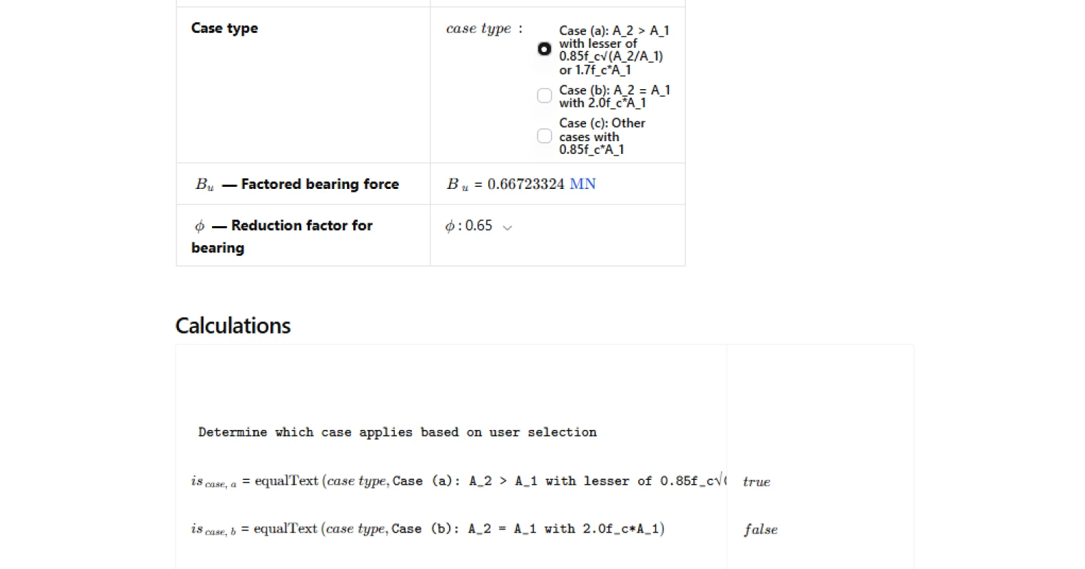
What is the difference between the three bearing strength cases in Table 22.8.3.2?
Case (a) applies when the supporting surface is wider than the loaded area (A2 > A1). The nominal strength is 0.85f'c·√(A2/A1), capped at 1.7f'c·A1. This accounts for the confining effect of the larger surrounding concrete. Case (b) applies when the loaded and supporting areas are equal (A2 = A1), giving Bn = 2.0f'c·A1. Case (c) covers all other configurations where neither condition is met, giving the conservative base value of 0.85f'c·A1. Select the case that matches your actual geometry — the calc does not auto-detect it from A1 and A2 inputs.
How is the A2/A1 frustum area ratio determined per ACI 318-19?
A2 is not simply the full support area — it is the area of the lower base of the largest frustum of a pyramid or cone that fits within the support, with its upper base equal to the loaded area A1 and sides sloped at 1 vertical to 4 horizontal. In practice, this means the frustum expands outward at a 4:1 horizontal-to-vertical ratio as you project down through the support. Measure your support dimensions and work back from the loaded area using that slope to determine the correct A2.
What strength reduction factor φ should I use for bearing?
ACI 318-19 Table 21.2.1 assigns φ = 0.65 for bearing on concrete, which is the default in this calculation. However, some design situations — such as bearing with confinement reinforcement or specific structural system conditions — may justify higher values. The calc provides a dropdown with options from 0.65 to 0.90 to accommodate these cases. Use 0.65 unless your project documentation and code interpretation support a higher value.
How do I set up the factored bearing force Bu in this calculation?
Bu is the factored compressive force transferred through bearing, calculated from the load combinations in ACI 318-19 Chapter 5 (typically 1.2D + 1.6L for gravity). You enter Bu directly as an input — the calc does not derive it from individual load components. Make sure Bu reflects the governing load combination for your member before running the check.
Why does the check flag a fail even when my areas look reasonable?
The most likely causes are: the design bearing strength φBn is less than the factored force Bu (the primary strength check), or A2 is entered as less than A1 which will fail the geometric check. Verify that you have selected the correct case type to match your actual A1 and A2 relationship — selecting Case (a) when A2 equals A1 will not give you a valid result. Also confirm your φ value is appropriate for the design condition.
Learn about the benefits of using CalcTree on engineering projects!