Calculate ACI 318-19 nominal horizontal shear strength (16.4.4) instantly. Checks Vu ≤ φVnh per Table 16.4.4.2. Try it free on CalcTree.

This template is not available yet. You can sign up and create it yourself!
Or let us know if you'd like to be notified when it’s ready:


No items found.
No items found.
About this ACI 318-19: Connections between Members - Nominal Horizontal Shear Strength (16.4.4) Calculator
This calculator determines the nominal horizontal shear strength at the interface between a precast element and a cast-in-place topping, or any other composite concrete connection, following ACI 318-19 Section 16.4.4 and Table 16.4.4.2. It routes the calculation through the correct code path depending on whether the factored shear demand exceeds the threshold for using Section 22.9, and applies the appropriate table row based on surface condition and reinforcement provision.
- Structural engineer — verify horizontal shear capacity at composite beam interfaces during member design, with the correct table row and code path selected automatically.
- Precast concrete designer — check connection adequacy between precast sections and composite slabs, iterating on contact width, reinforcement spacing, and surface roughness without manual table lookups.
- Plan checker or reviewer — trace every step of the 16.4.4 check, from threshold comparison through to demand ratio, with full input and output transparency.
This is an engineering-grade calculator built on CalcTree, designed to be saved, audited, and reused across project pages where composite concrete connections require code-compliant documentation.
More Info on ACI 318-19: Connections between Members - Nominal Horizontal Shear Strength (16.4.4)
Inputs
The calculator requires geometric, material, and reinforcement inputs that fully define the interface condition. The contact surface width and the effective depth of the composite section are entered directly, with the effective depth provided by the user from their own composite section definition per 16.4.4.3. The shear transfer reinforcement area and its spacing across the interface are needed to evaluate the reinforcement term in Table 16.4.4.2. The yield strength of that reinforcement and the lightweight concrete factor are also required material inputs.
The minimum shear transfer reinforcement area per 16.4.6 is provided as a separate input, as the template does not calculate it internally. The user selects the applicable table row based on whether the surface is intentionally roughened and whether minimum reinforcement is met. If the factored shear demand exceeds the threshold and Section 22.9 governs, the nominal strength from that section must be supplied as an additional input.
Calculation Method
The first step is computing the threshold force based on contact width and effective depth, scaled by the strength reduction factor. If the factored shear demand exceeds this threshold, ACI 318-19 16.4.4.1 requires the nominal strength to be taken from Section 22.9 rather than Table 16.4.4.2. If the demand falls at or below the threshold, the calculation proceeds through Table 16.4.4.2.
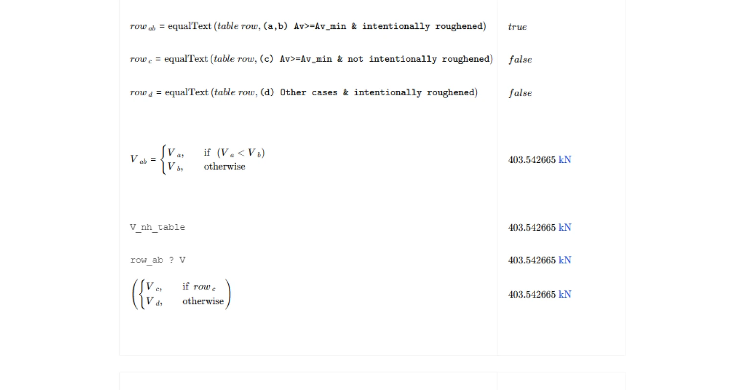
Within the table, the row selection drives the formula applied. For rows (a) and (b), where minimum reinforcement is provided and the surface is intentionally roughened to approximately 1/4 in. amplitude, the nominal strength combines a base stress term with a reinforcement contribution scaled by the lightweight factor, subject to an upper bound tied to contact area. For rows (c) and (d), the nominal strength reduces to a fixed stress multiplied by the contact area, regardless of reinforcement quantity. The governing nominal strength is then multiplied by the strength reduction factor to obtain the design strength.
Outputs and Design Checks
The primary output is the nominal horizontal shear strength, along with the factored design strength and the demand ratio expressing how close the interface is to its capacity limit. The calculator flags whether Section 22.9 was invoked, and which table row was selected, so the governing condition is always visible in the results.
Two checks are reported. The strength check confirms that the factored shear demand does not exceed the design strength. A secondary check flags when Section 22.9 governs but no value has been supplied for the nominal strength from that section, preventing a silent zero from passing the strength check. Both checks present as traffic light indicators for fast review.
Common Calculation Errors to Avoid
- Using the wrong effective depth — the effective depth d must reflect the composite section per 16.4.4.3, not the precast element alone; using the precast depth only will understate capacity.
- Omitting the minimum reinforcement check before selecting a table row — rows (a), (b), and (c) require that the provided reinforcement meets or exceeds the minimum from 16.4.6; selecting these rows without verifying that condition is unconservative.
- Assuming the surface is intentionally roughened without meeting the amplitude requirement — roughening must reach approximately 1/4 in. amplitude to qualify; a lightly broomed or formed surface does not meet this threshold.
- Leaving V_nh from 22.9 as zero when it governs — if the demand exceeds the threshold, a zero default will pass through the calculation silently and produce a misleading result; the secondary check in this template catches this, but users should always supply the correct value.
- Applying the wrong strength reduction factor — the phi factor for shear in composite connections follows ACI 318-19 Table 21.2.1; using a value intended for flexure or bearing will produce an incorrect design strength.
- Ignoring the contact surface cleanliness requirement — the code requires the interface to be clean and free of laitance regardless of roughening; this is a construction quality condition that must be specified on drawings and cannot be captured purely in calculation.
Engineering templates
Common calculators
Design guides
FAQs
What is nominal horizontal shear strength and why does it matter in composite construction?
In composite members such as precast beams with cast-in-place topping slabs, the two concrete elements must transfer shear across their interface to act as a single section. Nominal horizontal shear strength Vnh is the interface's resistance to that transfer. If horizontal shear capacity is insufficient, the composite section loses its assumed stiffness and strength, and the member may fail at loads well below the flexural limit. ACI 318-19 Section 16.4.4 provides the procedure to quantify and check this capacity.
How does the calculation decide between Table 16.4.4.2 and ACI 318-19 Section 22.9?
The threshold is phi times 500 psi times bv times d. If your factored shear demand Vu exceeds this value, the simpler table equations are not sufficient and you must calculate Vnh using the full shear-friction provisions of Section 22.9 instead. The template computes this threshold automatically and flags which path applies. If 22.9 is triggered, you supply Vnh from a separate calculation and enter it as the input V_nh_22_9.
What is the difference between the Table 16.4.4.2 row options, and how do I choose the right one?
The row depends on two conditions: whether minimum shear transfer reinforcement Av_min is provided, and whether the contact surface is intentionally roughened to approximately 1/4 inch amplitude. Rows (a) and (b) apply when both conditions are met and give the highest capacity, including a reinforcement contribution term. Row (c) applies when reinforcement meets minimum requirements but the surface is not roughened, giving a flat 80 bv d limit. Row (d) covers other cases with intentional roughening but without sufficient reinforcement, also giving 80 bv d. Select the row that honestly reflects your detailing and surface preparation.
What value of effective depth d should I enter, and where does it come from?
ACI 318-19 clause 16.4.4.3 defines d for horizontal shear checks as the distance from the extreme compression fiber of the composite section to the centroid of the tension reinforcement in the precast element. This is a property of your full composite cross-section, not just the precast piece alone. You determine it from your section geometry and reinforcement layout and enter it directly as an input. The template does not calculate it internally.
How do I provide A_v and A_v_min, and what happens if A_v is less than A_v_min?
A_v is the total area of shear transfer reinforcement crossing the interface within the spacing s you specify. A_v_min is the minimum required area per ACI 318-19 Section 16.4.6, which you calculate separately based on your member geometry and concrete strength. If A_v is less than A_v_min, rows (a), (b), and (c) of the table are not available. You must use row (d) or the 22.9 path depending on your demand level. The template uses your row selection to apply the correct equation, so it is your responsibility to select the appropriate row consistent with whether A_v meets the minimum.
What does the demand ratio output tell me, and what should I do if the check fails?
The demand ratio is Vu divided by phi Vnh. A value at or below 1.0 means the interface passes. A value above 1.0 means the design is overstressed in horizontal shear. To resolve a failing check, consider increasing the area or reducing the spacing of shear transfer ties, confirming that the surface is intentionally roughened to qualify for the higher table row, widening the contact surface bv if geometry allows, or revisiting the composite load distribution to reduce the interface demand.
Learn about the benefits of using CalcTree on engineering projects!